

Melano87
-
Posts
45 -
Joined
-
Last visited
Content Type
Forums
Detector Prospector Home
Detector Database
Downloads
Posts posted by Melano87
-
-
I had seen this modification several years ago with R86 on a French forum.
I know that some French people had made this modification successfully but had not made (had no knowledge) of the C42 modification at the time.
I am tempted like you to remove this resistance.
For the voltage, my previous tests with a TDI plate (not SL) that ended in failure no longer push me to go higher in voltage than my 4x18650 (about 16.7V).
-
 3
3
-
-
3 hours ago, CaliGold said:
Here is switch installed. Tight space there. A little close to the caps lower down on board inside but cleared ok with no contact. Debating on doing the swing speed mod when caps arrive this week. @Melano87 mentioned losing depth on this mod?
@Geotech or @Jim in Idaho Did you guys notice any depth changes/losses on sweep speed mod? Thanks!

Great job !
For losing depth :
-
2
-
-
33 minutes ago, CaliGold said:
No worries. I'm sure we all have lives outside looking for treasure...
Do you notice and depth increasing on signals with this mod? Sensitivity to smaller targets? Please share your thoughts on the performance you've notice if possible.
Geotech recommends a 1k resistor in series with the switch to the test points. Learning as I go..
many thanks
Patrick
As I wrote on the post before, the gain in depth is undeniable and even surprising. For small targets I can't say because I don't hunt gold nuggets, I use it on the beach and on the ground for coins, jewelry etc.
On my TDI SL the mods performed are:
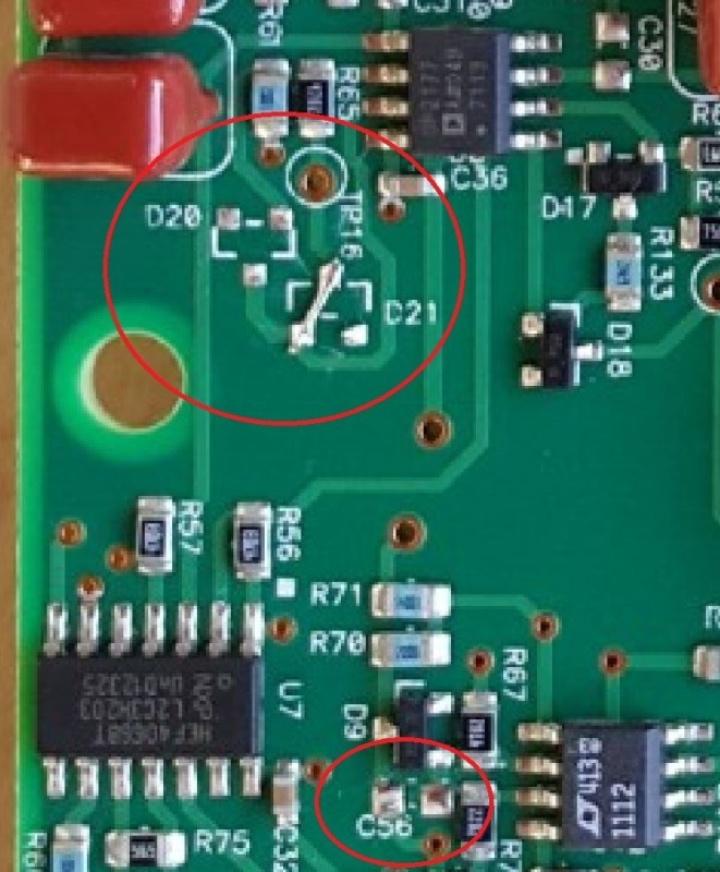
- C56/D20/D21
- C42 switch (without the 1k resistance)
- Potentiometer for the volume
- Battery 4x18650
The one not performed is the one on C20/C21 because I do not want to lose depth.
Carl is the best placed and most competent to talk about the TDI SL.
So I will add this 1k resistance.
Being in France on low mineralized lands compared to other countries, the results may be different.
-
3
-
-
15 hours ago, CaliGold said:
You did not use a resistor? This mod is stumping me. I've been told all sorts of tech stuff I don't understand. "across" "covers" "opamp abuse". Thanks
Sorry for the response time.
No, I had exchanged with several people, and I had not installed a 1k resistor in series.
And I use it like that.
Is this a mistake?
On air tests with modified battery (4x18650) fully charged, I get with the activated switch an additional difference of 5 to 10 cm depending on the type of target.
I did not make the modifications on the capacitors (C20/C21) because Carl had confirmed on a post that if we changed them, we gained in sensitivity but we lost a little in depth.
-
-
9 hours ago, CaliGold said:
@gflores71 on making the "jumper" on c42... How and what am I soldering together here? The two test points mentioned or? The nomenclature from the email got me a little confused... I see how the three pad diode smd was removed at d21 a "jumper" was completed but the c42 is a two pad resistor smd. Are we wiring the two c43 pads together after removal of resistor or one of the test points to one of the pads or both? I'm lost... Also,Does R75 resistor get removed/jumpered too? Thanks and sorry to pry but I'd like to complete this mod asap and get some testing / results posted for any other folks out there that were left looking for more sensitivity from the TDI SL.
@Jim in Idaho please freel free to share your knowledge on how this mod would be completed too (C42 and R75)
Thanks so much again to everyone.
Pat
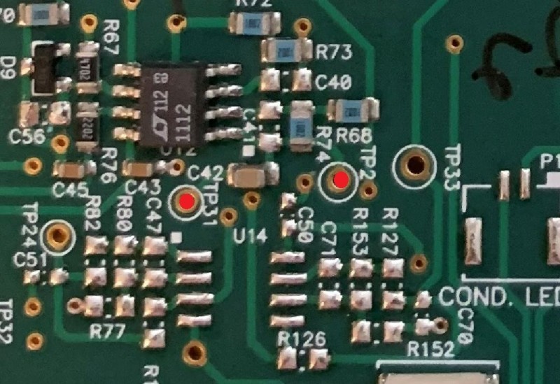
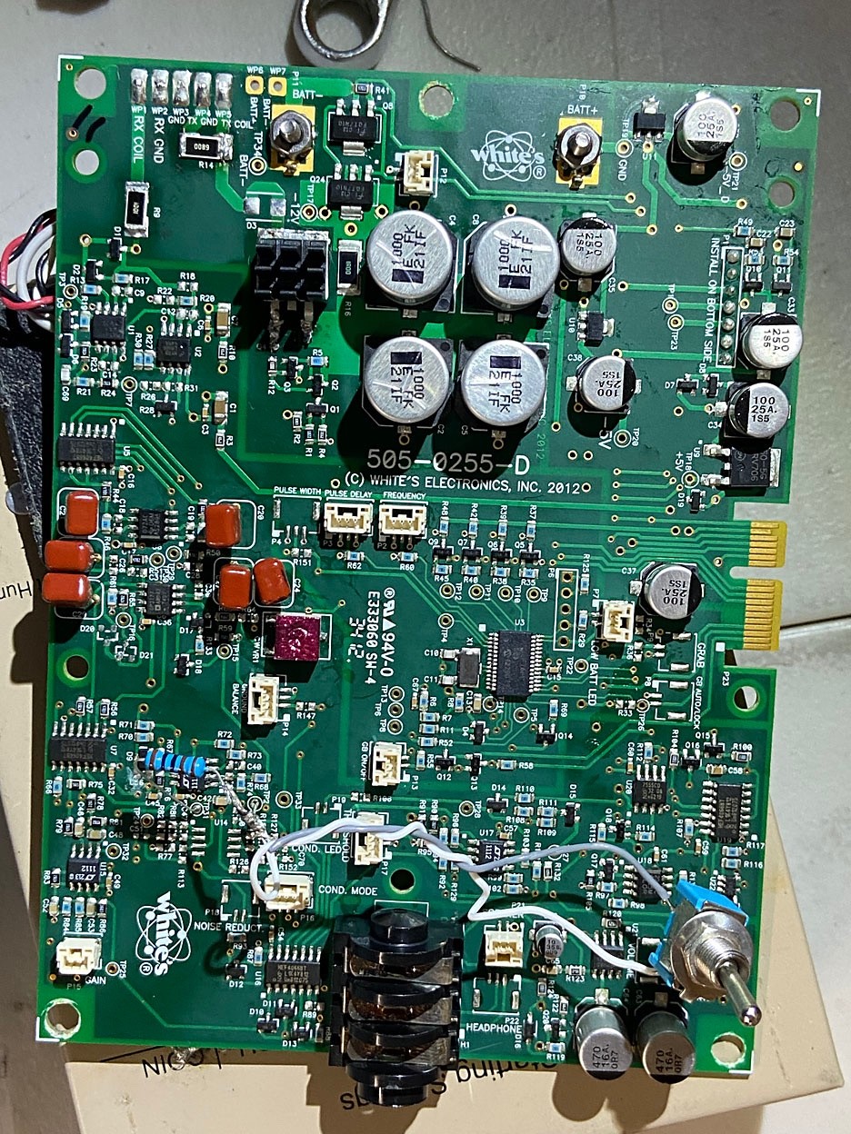
The jumper is made with the Test Points 2 and 31.
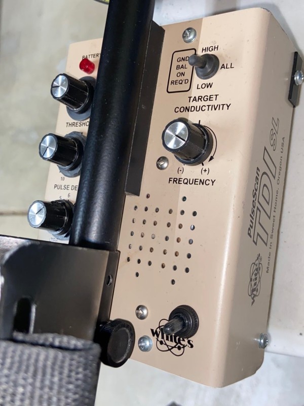
When I made this modification, I soldered a wire on the TP31, a wire on the TP2, I installed a switch (2 positions) next to the speaker (only place really available), I twisted the two wires up to the switch.
Why a switch? Because as the gain increases you have to be able to “control” it and there are places where it is difficult. So when I need it and possible I put it in the ON position.
Don't touch R9 - R75 - C42
On TDI SLs manufactured after 2015, D20, D21 and C56 are absent (modification taken into account by Whites). On those before 2015 they are present.
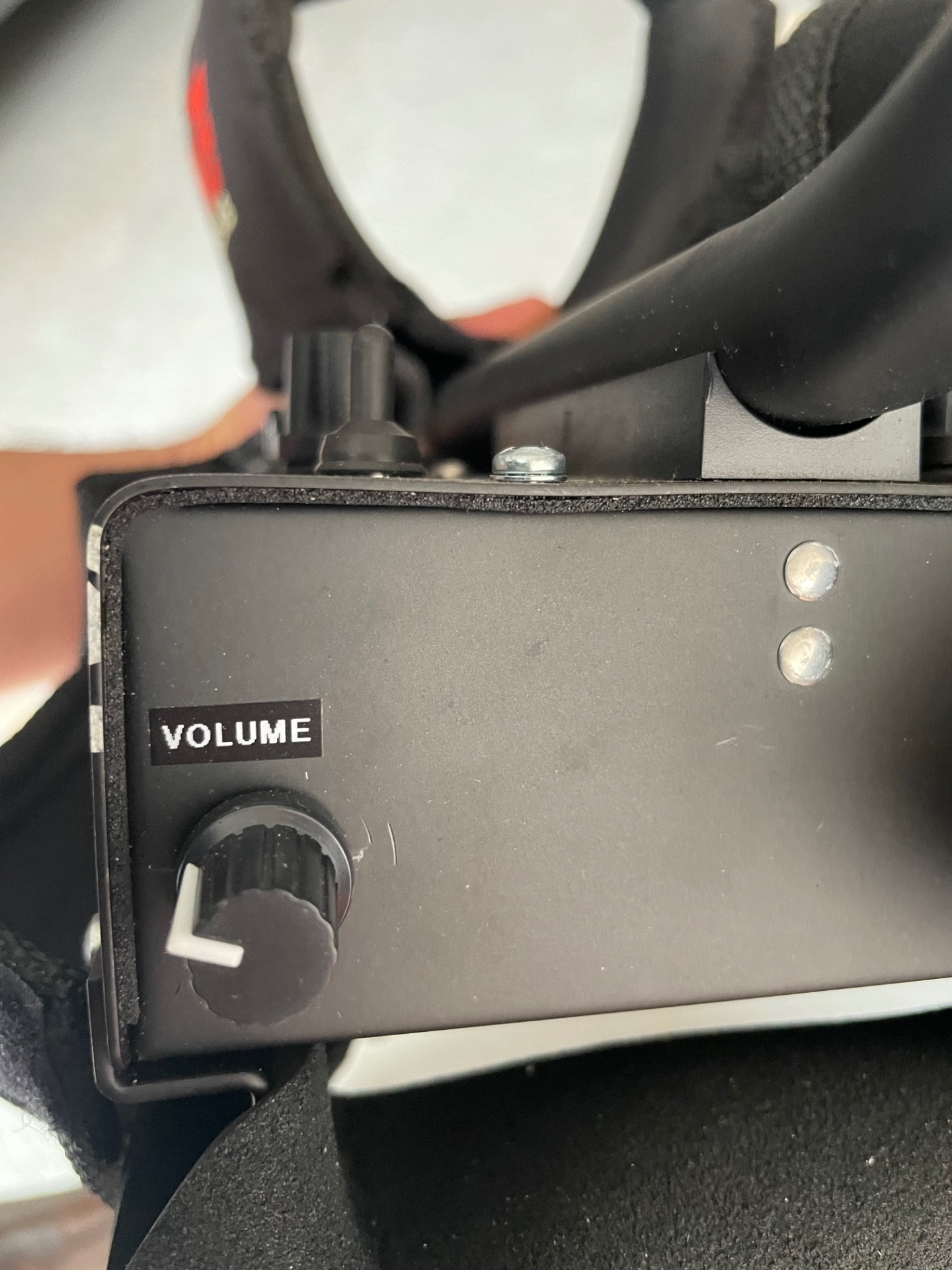
I also installed a potentiometer for adjusting the audio volume (like on the Beach Hunter)
-
3
-
-
Hi,
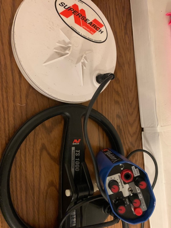
I have a problem with my Musketeer X, I bought a used TS1000 Treasure Searcher coil (not the Slimline) which according to the seller works wonderfully on his Musketeer Advantage.
But on my Musketeer X, as soon as I plug it in it emits a brief and repetitive sound to infinity.
My question are the coils of the Musketeer Colt / Adavantage / XS etc compatible with the Tribune / Sterling / Musketeer X?
I checked at the ohm-meter and I can't find any value between terminals 4 and 5 (while on my original Supersearch, I get a value around 100 and a few ohms).
Thanks.
-
3 hours ago, Jeff McClendon said:
For those of you who may not think or believe that Minelab cares about their customers or that they pay attention to these forums, I had a very nice, lengthy phone call from one of the Equinox 700/900 design engineers tonight (4/28) in order to talk about the experiences I was having with the Equinox 900 that I own.
Thanks to everyone who contributed to this topic and who kept it real, no nonsense and as factual as possible. Minelab does care about the experiences we are having especially with new models and also when they are reported in a level headed way.
For you GPX 6000 owners, I did give the gentleman that called me a huge thanks for the speaker/audio/EMI mod and I gave him and Minelab a special request for a small DD coil for the GPX 6000. Maybe it will happen.
later,
Jeff
Good news Jeff.
-
It's ok, Gain 100k 1%, Volume 100k 5%.
-
Hi Jim and Sven,
Sorry for my question maybe my english isn’t very good and so cell was not understood.
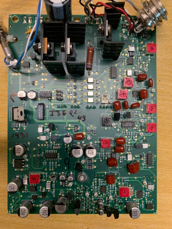
I don't have a Beach Hunter TDI, I wanted someone to tell me the value of the resistors that are of the Gain and Volume potentiometers.
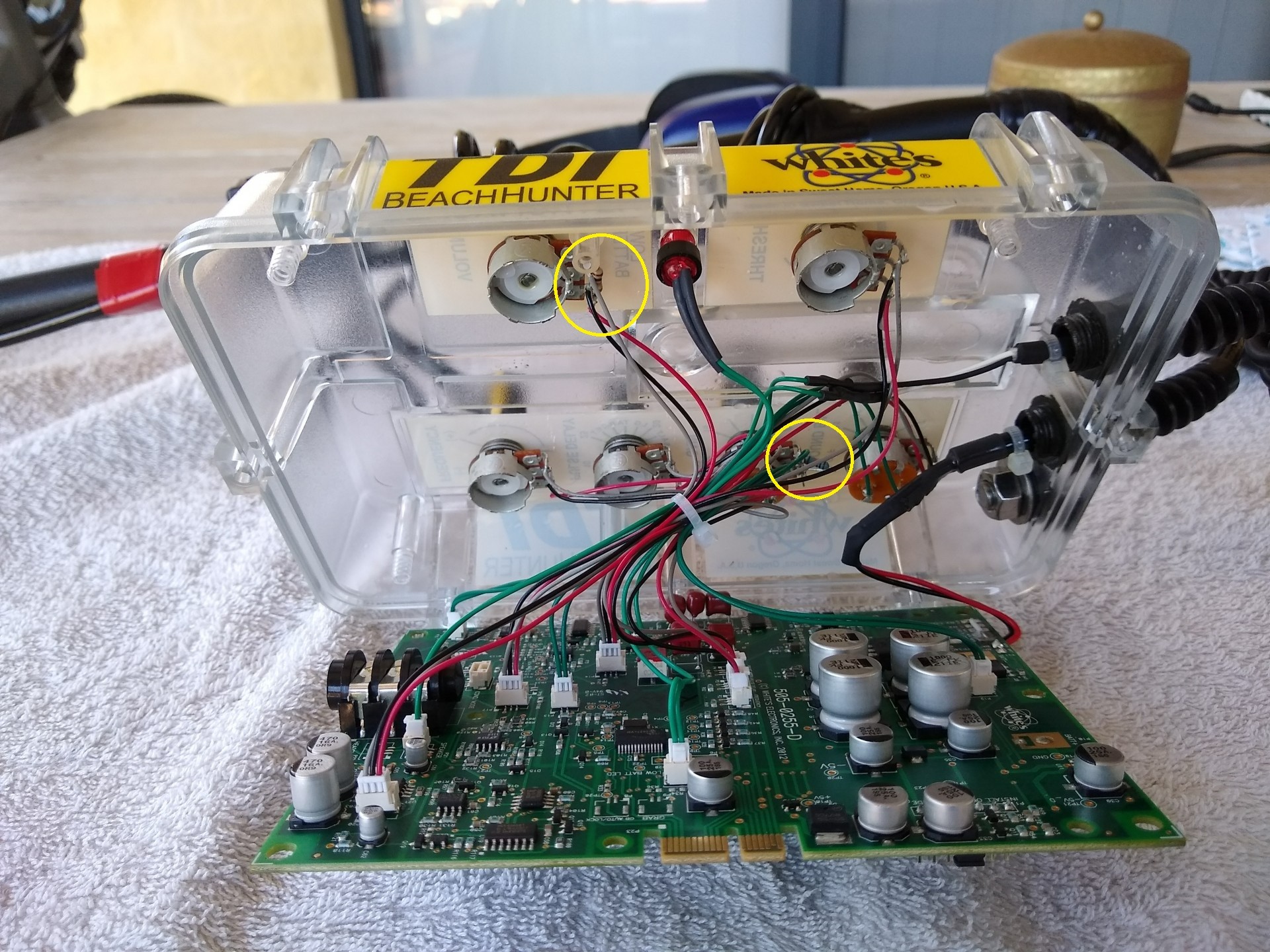
There on the photo I can see these resistors from afar but not entirely.
Thanks.

-
Hi,Someone who has the TDI Beach Hunter could tell me the value (color code and %) of the resistors behind the Gain and Volume potentiometer, and a photo of each please?
Thanks.
-
Hi,
I wanted to share a simple website from an enthusiast French guy.
Perhaps unknown across the Atlantic, listing many old brands of metal detectors, with photos etc.
For the nostalgic
-
8
-
-
-
7 hours ago, karelian said:
Checking again, single section over discharge detection votage is 2.75/2.85v. Multiplye that by five give us a cut off range of 13.75 and 14.24. Tested mine came in just under 16volts cut off and max 21.5v.
Single section max charge comes in between 4.18 and 4.22v, so between 20.1 and 21.1, tested at 21.5v..
There are numerous 5 x 18650 pcb's available so the link is not the only option available. Claimed specs vs tested results do differ. All the best.
Thanks.
-
On 9/28/2022 at 6:30 AM, karelian said:
5S 15A BMS PCB Protection Board 18650 Charger Li-ion Lithium Battery Cell | eBay
21.5 volts on full charge with cut off at 16 volts.
Big box Tdi, Pro etc same battery system. You can always rebuild your battery with new cells.
Lots of PCB choices, just make sure the specs are the same. All the best.
Hi,
Is the link given a protection that cuts to 18v? Not at 16V?
Thanks.
-
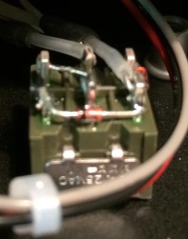
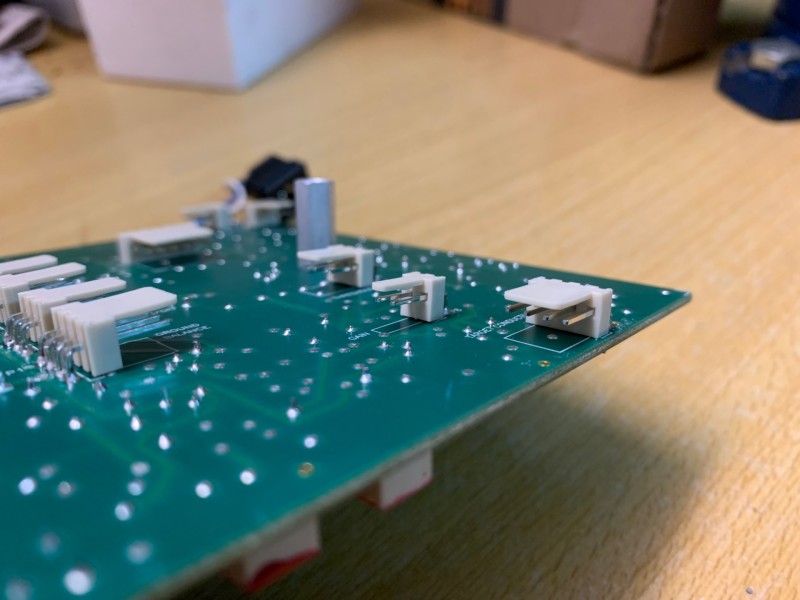
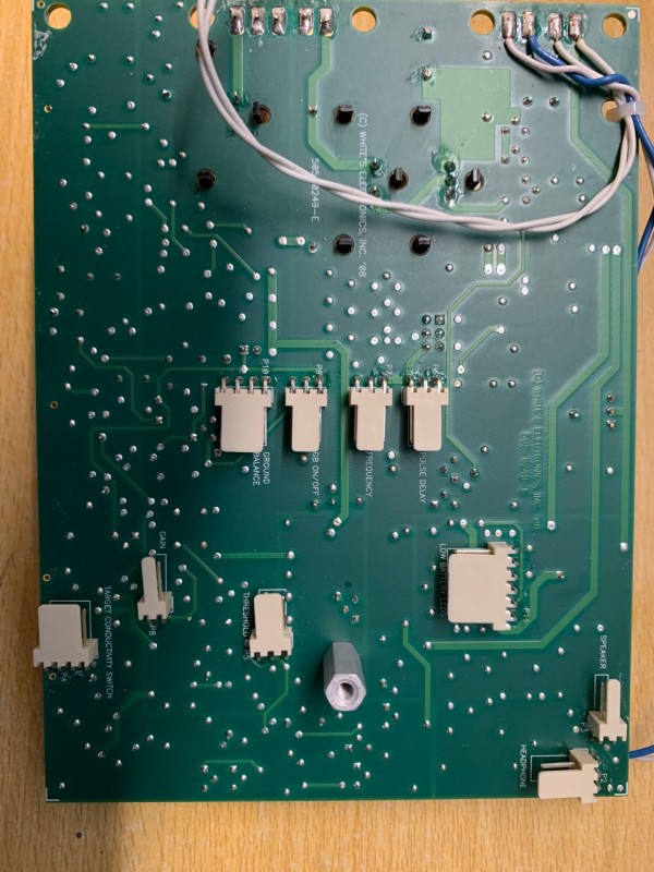
I came across photos on another forum showing the wiring of connectors and switches on the Pulse Scan. (The photos are like this on the site, not of very good quality)
I don't understand why zener diodes everywhere.
Is the wiring of the conductivity switch just unlikely?
I have the impression that on the white connector the two wires in the middle are connected via a zener diode (?) One on the wire on the right and one on the wire on the left... I don't understand anything.
-
52 minutes ago, Geotech said:
I'm not sure what you mean by "turntables."
In the TDI, C59-C60 (same as C20-C21) are already 0.22uF but you could decrease them to 0.1uF to equal the SL speed improvement. The 2 caps need to be matched to 1% or better. The TDI has no C56 or D20-21, and C42 is C50 in the TDI and can be shorted.
I'm not familiar with the other mods in Jim's post. I think the preamp replacement was the LME49990 but without some other changes just replacing the opamp won't do much.
« Turntables », my english is poor… Board
Very interesting, thanks Carl.
Will lowering the two capacitors to 0.1 lead to something else (loss of depth)?
Do you think this is useful as it was done by Reg on the TDI SL?
-
25 minutes ago, Jim in Idaho said:
Those mods apply to the TDI SL, not the TDI Pulse Scan. The mod for the original TDI's was to smooth the threshold.
Jim
Hi Jim, thanks,
What are the mod, because despite my research I can't find an explanation?
David
-
10 hours ago, Geotech said:
Yes, 3 positions, on-off-on.
Hi Carl, thanks again.
I still had a few questions:
- Do the Pulse Scan TDI/TDI Pro and TDI SL turntables have big differences (performance), if so which ones?
- Are the Reg changes applicable on the Pulse Scan and should they be made to improve? If so, what are the matches of the C20-C21 capacitors to be set to 0.22uF, the C56 capacitor to be removed, D20-D21 diodes, jump over the C42?
Regards.
David
-
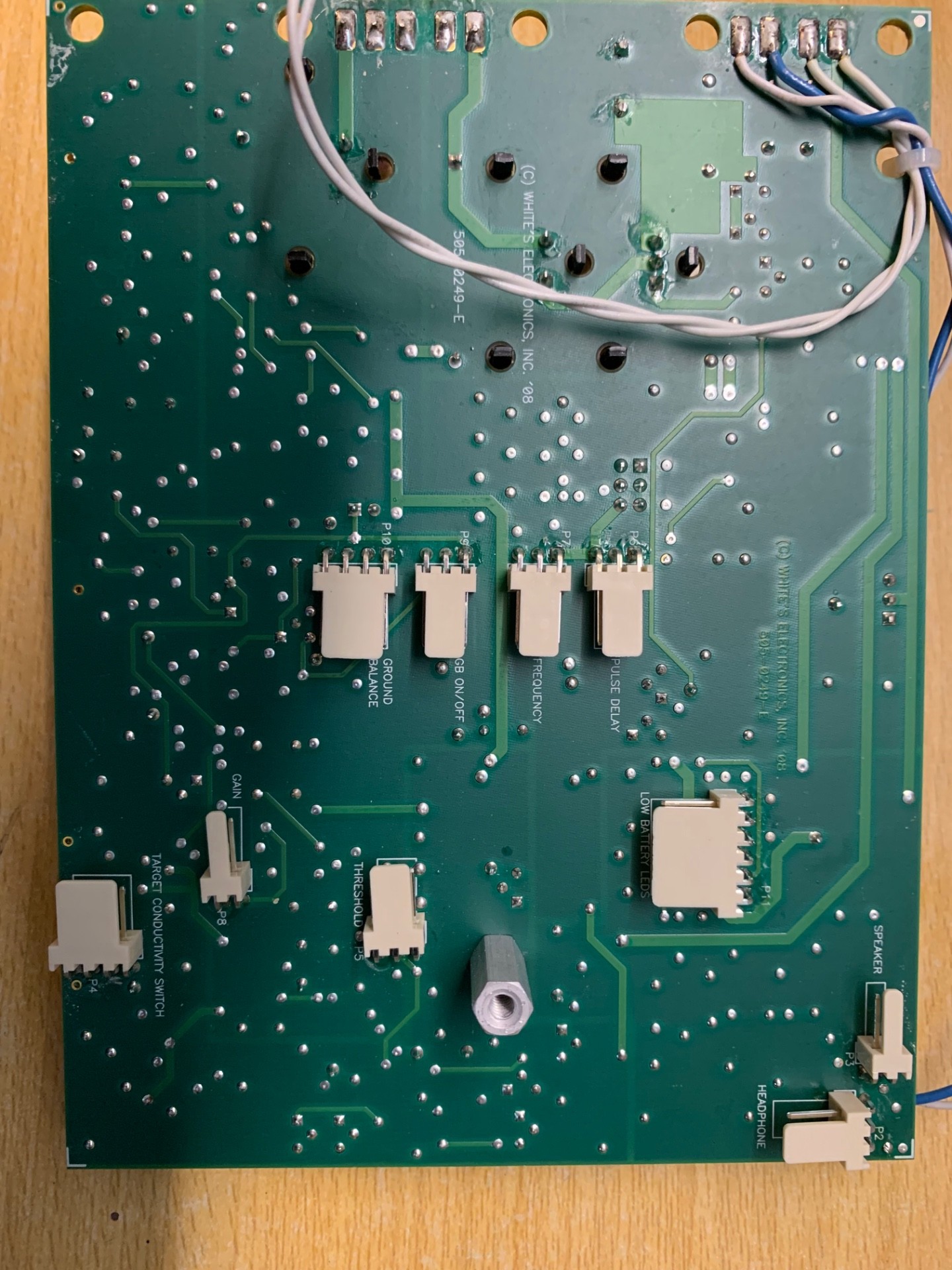
On 9/5/2022 at 4:46 PM, Geotech said:
All pots are mono. The pin connections are all linear, that is, outside-middle-outside on the pot (or switch) is the same on the connector. This means you will have to figure out which outside connection goes where but that's pretty easy once you fire up the circuit. If the pot operation is backwards, swap the outside pins. Sorry, I don't have a diagram or a pic.
Pulse Scan TDI
Is the target conductivity switch an ON-OFF-ON?

-
1
-
-
Thanks Carl and Steve.
-
Thanks again Carl, I understand.
I had one last question, what is the difference in wiring on the "Pulse Scan" where there is the "Ground Balance" potentiometer and the "GEB On Off" switch and the TDI Pro with the two potentiometers "GEB Fine Off" and "Coarse GEB" ?
The "GEB Fine" of the TDI is a potentiometer that has a switch and comes in the same location as the "GEB On Off" switch of the Pulse Scan Pro?
What is the value of this switch potentiometer?And also Coarse GEB = Ground balance ?
Thanks.
David
-
Hi,
Many thanks Carl,
Ok for the plugs. But the potentiometers, none is "stereo" only mono.
Also, how do you know which pin of the potentiometer/switch goes where on the plug?
Thanks.
David
-
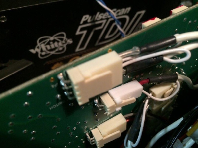
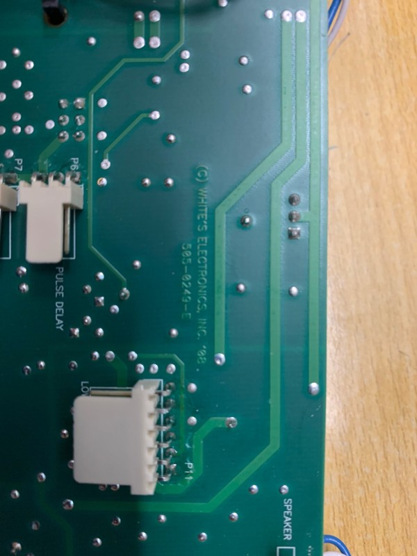
Hi,
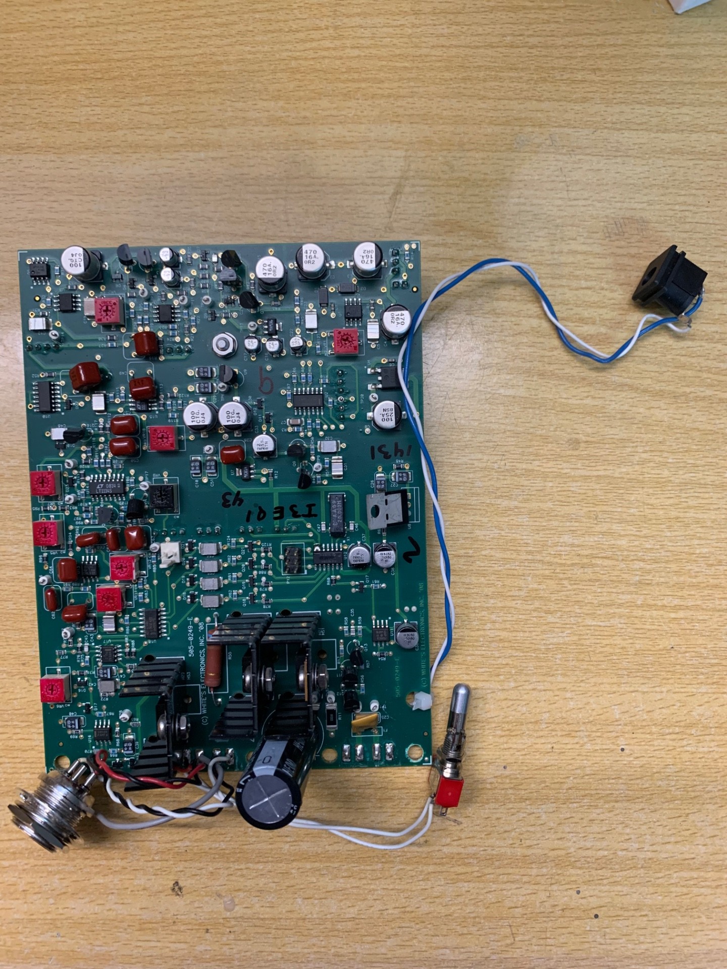
Having recovered a Whites TDI motherboard (not SL) and having a coil.
I would like to reconnect it with potentiometers and switches.
Does anyone have photos showing the wiring/colors of the switches and potentiometers on the plate and the values/types of the potentiometers (B100k etc.) and switches?
Thanks.
David


Reg Mods Update
in White's Metal Detectors
Posted
Likewise I await your results and tests