


Geotech
-
Posts
590 -
Joined
-
Last visited
Content Type
Forums
Detector Prospector Home
Detector Database
Downloads
Posts posted by Geotech
-
-
-
The MX7 and MX9 as I had defined them were never released. A different MX7 was released after I left.
-
 2
2
-
-
Here are my original definitions for the MX5/7/9:
From the MX5, the MX7 added freq offset, Relic mode, more tones, and some advanced features. The MX9 added Prospecting mode, track lock, another tone option, and some more advanced features. The MX7 that was actually released (in the MX Sport enclosure) is a different animal than what's in the table above, it has some features from both the MX7 and MX9 above.
-
2
-
-
No, I built one and got the measurements I needed.
-
2
-
-
29 minutes ago, Chet said:
Perhaps this is one that only works well on the bench;
Paul's concepts are pretty solid. I'm currently working on a similar project.
-
5
-
-
- Popular Post
- Popular Post
9 hours ago, jasong said:The GPZ is kinda a PI/VLF hybrid on steroids in some ways already, though I guess neither truly.
I'm unsure why discrim can't be implemented on ZVT...
ZVT is PI, not VLF. It has a high slew followed by a dead time, another high slew, another dead time, etc. You only get a reactive signal during the high slew and a reactive signal is required for discrimination. But all the sampling is done during the dead time.
8 hours ago, phrunt said:So, you're saying Garrett has it sitting in their storage room in among the boxes marked "whites old stuff" and they could continue on with the project? It is something someone else could take over or is it something that would be near impossible without your involvement?
Would the code you have written be able to run on today's hardware or would it need redone due to obsolete components?
I don't understand why if this was in existence the project would not be resumed, as it does sound like a very beneficial product that would sell very well.
...
So, what makes the half sine design so special over the current market offerings? What are the benefits of it over the detectors we currently have? I know very little to nothing about it, well before my time when this was taking place, a real shame it didn't hit the market though.
Yes, Garrett could resurrect it. I've heard through the rumor mill that Garrett looked at it but either didn't know what to do with it or wasn't interested. As @tboykin mentioned above, White's also didn't know what to do with it. I wrote a patent for it and the patent gives all the info needed to understand it, and I left a fully working prototype and all the firmware (in C, portable to any micro). The turnover was high at White's and with new engineers this would have been an advanced project. I have no idea what the engineering landscape looks like at Garrett, but I'm sure they could figure it out.
Half sine is a true hybrid technology. You get a full VLF response at the same time you get a PI response. You can also run it multifrequency and multi-pulse at the same time. I think my prototype was single frequency but I also built a 3-frequency transmitter, just never hooked it up to a receiver.
8 hours ago, EL NINO77 said:As for the hybrid detector, the Aka Smart pulse detector has been on the market for a while, which is a hybrid PI-VLF detector...
After my earlier post, I was off to the dentist for a root canal. While sitting in the chair I thought, waitasec, didn't someone market one of these? Thanks for the reminder.
8 hours ago, Steve Herschbach said:AI does not change the fact that for every good target there are countless trash targets that look exactly the same to the metal detector.
Not only that, but on the bench you can swing targets and get nice looking responses. But then you put the coil to the ground, and it's just a mess. I've seen engineers who thought they had designed a great detector, and when they get it in the field they just start crying. All that said, I think AI will slowly work its way into detectors, but don't expect a whole lot from it. And metal detectors tend to be late adopters of technology, so don't expect it soon.
This topic of VLF+PI has come up before, and every time it does I get all worked up and wanting to jump back into those old designs. But then I remember I haven't finished writing that damned book, so I exercise some self-restraint and go back to writing. The book is almost done, and I will move these projects to the top of my to-do list. Should be fun.
-
17
-
 6
6
-
- Popular Post
- Popular Post
At White's I designed an MXT+SMPI circuit, got the TX, coil, and preamp working but then abandoned the project for the far more promising truncated half sine. With MXT+SMPI you get one or the other but not both at the same time. With half sine you get both at the same time, and the option to do multifrequency/multipulse. I got the half sine project running and that's when I left White's. No one ever continued the project.
-
20
-
 2
2
-
No idea, just use whatever gives a just-snug fit. Too much washer or too little will stress the ears. Probably that's what this is all about.
-
1
-
1
-
-
So far, I've only done cross-sectional analyses of circular coils. I'm not sure it can do more complex shapes. It appears Elmer can, another free FEM tool, but I haven't found any idiot-training videos for Elmer as yet. I'm also to the point where I need to do some 3D analyses so if I find anything usable I'll post it here.
-
Jason: Yes, the anti-Helmholtz is a bit like a Halbach array. I once looked into a Halbach array for a medical detector. I don't know any way to trade off near-field for far-field, as far-field always follows near-field. "There is no free lunch."
Chet: I'm using FEMM which is free and there are some Youtube instructional videos. After going through it a couple of times and setting up a few "starting point" coils, I can now do a sim in about 5 minutes.
-
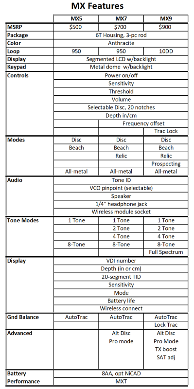
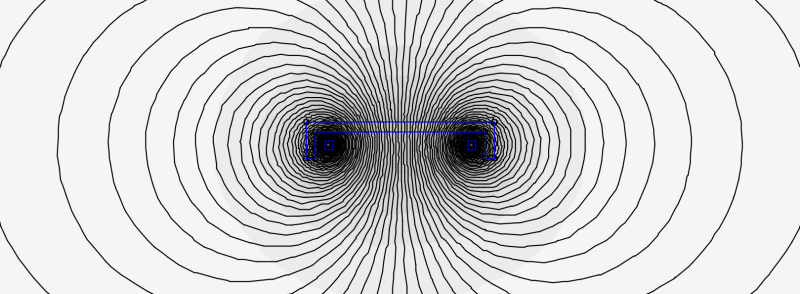
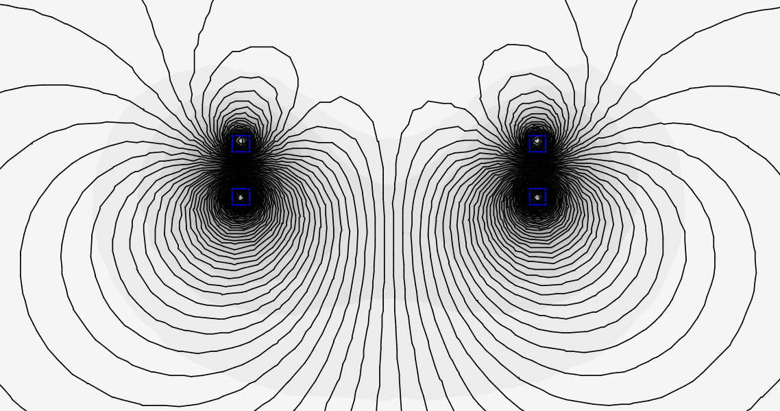
Any time you place ferrite near a pancake coil it causes the flux lines to bend more. This is why mineralized ground reduces depth, it increases the flux curvature and reduces flux density at depth. Placing a ferrite shell on top of the coil certainly does what you envision (reduces the top-side field); at the same time it increases the bottom-side flux density very close to the coil but this advantage is quickly lost and at depth the flux density is reduced. Here is an FEM plot:

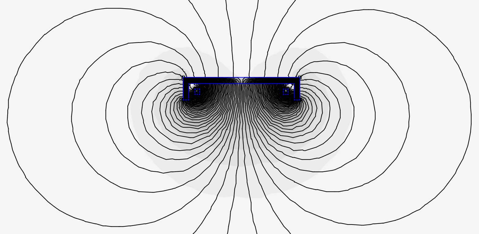
Here is the same coil with the ferrite set to air:
It's possible the ferrite-shelled coil would be good for shallow tiny nugget detection.
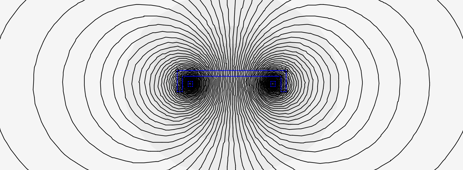
Another (lighter) possibility is to design an anti-Helmholtz coil, where an anti-phased bucking coil placed just above the TX coil to "focus" the field downward:

Unfortunately it tends to also reduce flux density at depth compared to just a single TX coil.
.
-
A very interesting thread.
Jason: No, adding ferrite won't help, it'll just make the coil heavy. The only exception is in a pinpointer where a ferrite rod is used to concentrate the field. This works well in a PI or energy theft pinpointer which use a mono coil. When you use an IB coil the RX must be air-cored so, ferinstance, the White's TRX has the TX coil wound on a ferrite rod but the RX coil is on a plastic bobbin. If this concept were used in a regular detector, you would have a big long ferrite for the TX coil with the RX underneath, so the coil is 8" thick and weighs 20 lbs.
Chet: Have you ever tried using FEM software?
-
Is that a Garrett in the first pic?
-
It's a custom made display, you can only get it from Nokta.
-
I have little practical time with this coil but I did take a prototype to the coast to try it in the surf. I found that it slices through water better than any other coil I've ever tried. Unfortunate that there is no MF detector to bolt it to.
-
8 hours ago, mcjtom said:
Could you describe the 'double ring' of iron at depth (as opposed to nonferrous single ring as iron at depth)? Near-surface ferrous targets could double (or triple) ring for different reasons - does it sound different than the 'double ferrous ring' at depth?
p.s. A question probably for @Geotech: does it make sense to explain the 'double ring' of iron target at depth as:
1) the Tx magnetic field magnetizing the ferromagnetic target by induction and the target returning the signal immediately, in phase,
2) the same alternating Tx field inducing eddy currents in the target which in turn produce Rx magnetic field, but this time the return is delayed.
The delay between the two returns changes the way how a target sounds?
I don't know how it sounds on the Equinox (and possibly on Vanquish by association), but I tried to imagine why deep iron should 'double beep' but deep nonferrous could show like iron but not 'double beep'...
It's the same issue as described here. A shallow iron target will double-beep even with a brisk sweep but with deep iron the two beeps blend together (due to the geometry of depth vs coil size) unless you slow down the sweep rate.
Deep non-ferrous can start to look ferrous because the ground response (with is almost purely positive-reactive) overwhelms the now-tiny negative-reactive portion of the non-ferrous, so that the target's reactive signal ends up looking ferrous. This is more likely to happen with low conductors than with Big Silver Coins. It also depends on the quality of the ground filters. Less likely to happen with the old 4-filter designs, which no one makes any more (AFAIK).
Shallow non-ferrous can double-beep because as you get really close to the RX coil the edge of the coil becomes more sensitive than the center. Gold prospectors use this to "edge-detect" really small nuggets with PI mono loops.
-
I need to make some pattern measurements on a Cleansweep coil for my book. If anyone has one (either 4pin or 5pin, doesn't matter) and willing to loan it, I'll pay shipping both ways. I have a Cleansweep which has been sitting in a box for 10 years, I pulled it out and the null has shifted so badly it is unusable.
-
21 hours ago, phrunt said:
Why has it taken so long for other detectors to do the same?
Dunno, I proposed this at White's and again at FTP, no interest.
-
It's single frequency in that it only transmits a single frequency square wave. But that square wave has odd-order harmonics and the 3rd harmonic can be demodulated as a pseudo-second frequency and used for salt cancellation. Because the 3rd harmonic is much weaker, it does not make an effective second frequency for the purpose of detecting targets. That is, if you transmit a 5kHz square wave, the 15kHz 3rd harmonic is useful for salt cancellation but otherwise the detector performs mostly like a 5kHz single frequency.
If this sounds familiar, it's exactly how the Fisher CZs did it back in 1991.
-
1 hour ago, markinswpa said:
The way I see it SMF is 6 year old technology and most agree that its peaked.
SMF is either 23 or 33 years old, depending on your definition of SMF. And I would not be so sure it's peaked.
-
That confirms what I've heard: high-end multifrequency with color display. From what I know they started work on this 12-13 years ago. It'll be interesting to see if they borrowed anything from the V3.
-
Apparently Republic is the gold capital of Washington State. 8 million ounces and still going. But few places for prospecting, it's all deep hard rock stuff. Almost ended up in White Salmon, gorgeous area.
-
Where abouts in Washington?
-
I posted a reply to Woody's video. The ferrites shield the solder connections so they don't light up with sudden changes in ground mineralization. Woody mentions this late in the video but doesn't seem to think that's what they're for.

Amazed At How Quickly White’s Discussion Faded
in White's Metal Detectors
Posted
White's made a lot of mistakes, not releasing the MX9 ranks pretty low.