


Chet
-
Posts
219 -
Joined
-
Last visited
Content Type
Forums
Detector Prospector Home
Detector Database
Downloads
Posts posted by Chet
-
-
On 5/3/2023 at 4:59 PM, jasong said:
How deep will that 58x28" hit a .22? Mostly just near surface?
Yes the .22 bullets were just a few inches deep.
My latest coils to be tested the next time in the field are below. One is a 6” mono for the GPX 6000.The other is a 8” concentric for the GPZ 7000.
-
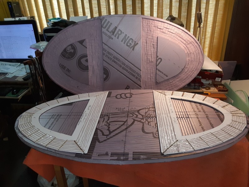
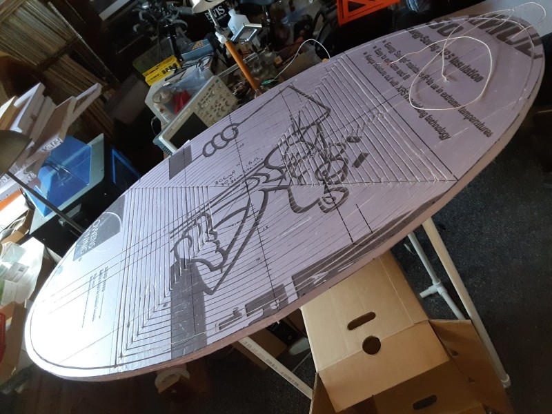
Large coils are on the back burner for now. Below is the second one 58" x 28" that I put together. The electrical specifications are the same as standard coils. I wound both the transmitter and receiver with wide spacing between turns. This cuts down the coil capacitance and improves the Q (quality) of the coils.
It started out to be a drag coil but since I don’t have a ATV and Northern Nevada has so much sage brush it became a large push and pull coil. It weights approximately nine pounds. It has some serious problems that prevent it from being a good coil. My pick, the detector body and other stuff are too close to the coil. Going over rising and falling ground sounds similar to swinging over damp salty ground. The coil cable sounds off when it is moved up and down. The windings are glued down and the foam board is rigid so it doesn’t have any bumping noise.
It picks up shallow .22 bullets as double hits as each receiver coil passes over them. Air testing above the coil; one ounce gold coin around two feet; coke can approximately seven feet.
Since coke can size nuggets are so rare I am working on 25 to 30 inch coils. Improving depth on one ounce and below is the goal.
-
A friend worked at one of the ELF transmitter sites when he was in the Navy in the 1950s. It has miles of antenna wires and miles of cables buried in the ground to essentially make the earth the antenna. It was driven by high transmitter power that charged your car’s surface so there were spring supported grounding rods in each parking space to park your steel bumper against before you stepped out. I wander what they do now with plastic bumpers and plastic splash guards under some cars?
The wavelength of ELF signal is many miles long. Submarines receive the signal by deploying a long floating wire antenna. I don’t think small loop antennas would pick up much signal especially for making any kind phase shift or signal strength comparisons between sine waves that have their peaks and valleys many miles apart. It’s similar to the needle in the haystack problem.
The largest PI coil I recall was one on the Meteorite Men TV program. They had a large PVC drag coil that detected a huge deep meteorite in a Kansas field. It was a known area for large meteorites.
You have probably seen some of the power equations before; it is hard to gain much by brute forcing more energy. The concern on detector weight rules out larger coil wire gauges and the extra battery weight to power a heavy coil. It is practical to make gains in receiving and data processing. That is where Minelab has made the improvements.
I have built a number of experimental mono coils of varies sizes between 6” to 48” for the GPX 5000 and the GPX 6000. I have built two experimental drag coils for the GPX 5000 and GPZ 7000. I am aiming for a size that has a sweet spot for a 1 oz. nugget. I think my next and hopefully final coils will be a 25” or 30” mono for the GPX 6000. And a similar size Hybrid Concentric coil for the GPZ 7000. The Hybrid Concentric has an outside receive winding with the transmit winding spaced much closer than the normal practice of 50%. The receive null coil is almost against the transmit coil. I have already built this and had it working. But the glue that I used was water based and soaked into the Litz wire windings and never completely dried.
-
There has been some work similar to what are describing used to identifying mineralization and discontinuities or possible ore bodies in a localized area. Submarines listen from any ocean for orders from Extremely low frequency (ELF) of 1 Hz to 300 Hz radio signals. I think someone has experimented with the Pulse Induction arrangement. The problem with trying to benefit from large transmit systems is the wide dispersed transmit signal is too weak. The feeble energy induced into and retransmitted by a large nugget would be undetectable.
-
The receiver frontend was operating as close to minus 273 degrees Celsius as could be achieved outside of a laboratory environment. This was to prevent noise from electron flow in the receiver wires and components. On rare occasions the cryogenics unit would fail causing a 3 decibel loss in receiver signal to noise ratio. This is a real loss when you are trying to detect and track incoming Russian submarine launched missiles.
-
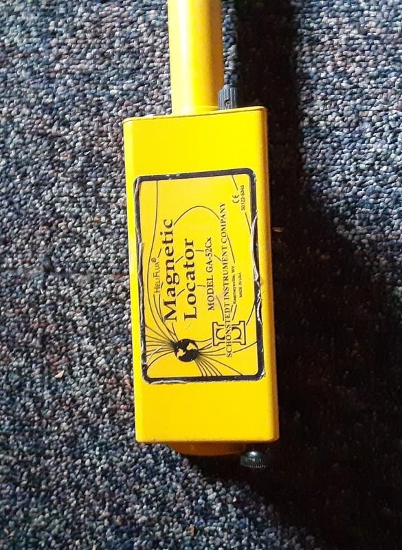
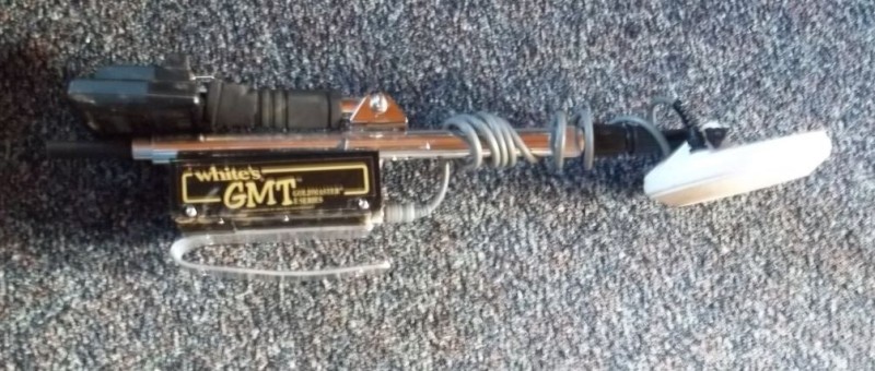
I passed a rare earth magnet along the right side of the housing. Just below the GPX lettering it sounds off like a target passing under the coil. There is probably and inductor or transformer at that location. The speaker magnet inside the phone is probably affecting it a similar way. Nonferrous materials will not shield magnetic fields. So it would require tin or powered iron epoxy for shielding if it was a serious problem.
Much of the EMI we are experiencing is coming from many sources that are hundreds and thousands of miles away. It is bouncing off the ionosphere and varies in intensity with changes in the ionosphere.
In my days of working with cryogenically cooled radar receivers we had a constant noise/EMI problem that we could not fix. It was the distant noise/static from the big bang sill travelling through space.
-
1 hour ago, jasong said:
The 6000 coil screams on it when I drape it directly over, then rapidly dies down and stabilizes.
The automatic ground balance is probably adjusting to the material similar to mineralized ground. It would probably bias or reduce the ground balance circuitry.
I just now tried some indoor of experiments. I sanded the clear finish off of a lower carbon fiber shaft and measured the resistance to be 25 to 35 ohms. It is not detected when waving it over the GPX 11” coil. I put my Galaxy A10e phone against the GPX 6000 housing and did not hear any additional noise. I removed the GPX 6000 arm rest and wrapped the entire housing with heavy aluminum foil, leaving a small opening for the speaker sounds; it did not reduce the EMI noise. I will try these tests again when I get back to the desert.
I played with a large sheet of aluminum foil placed on top of cardboard boxes. I got a similar effect that you got with your quarter test. But as I reduced the foil distance the detector quieted down similar to what Woody was accomplishing with the copper mesh. The distance was very critical; just a slight change would cause it to go completely silent or go full EMI mode. The copper mesh may have insulated strands that would have less effect than the solid foil.
In the desert if the EMI is low I try to run at Manual 10 when EMI gets annoying I go to Auto 2 which is much of the time. The last time I was out it was running so quiet that I checked it on my test nugget to make sure it was still working. About an hour later it went crazy. Auto tuning did not help. I looked around and spotted some distant aircraft. As they got closer I could make out that they were three twin engine Osprey helicopters. It quieted down again after they disappeared behind some mountains.
Other than the known speaker EMI problem I think we are just dealing with a very sensitive detector that was designed to detect very small nuggets. I am content to accept that and enjoy the light weight and ease of operation. I look forward to the seeing what is in the next model. -
Jason
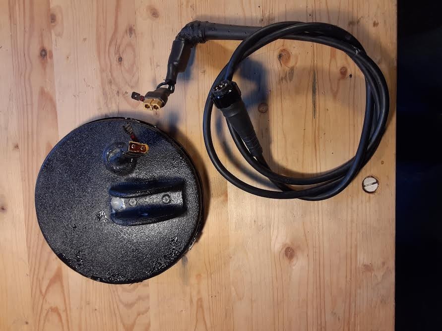
Conductive shielding such as copper mesh can be used. Some of the early BFO and VLF detectors used aluminum foil or copper mesh. One even used a thin wall copper pipe with the windings inside. There must a gap such as a very thin slice of pie or slot removed in the shielding somewhere within the 360 degree circle. The gap prevents the shield from becoming a shorted turn. The entire coil and shielding must encapsulated in epoxy or foam to prevent any movement between the coil and the shield when bumped against anything. In the videos you can see how the slightest movement of the copper mesh causes problems.
Since those good old days lol by rule of thumb it was determined that any shielding material that could be detected when passed over the coil should not be used. It was found that a graphite coating with a resistance of 50 to 150 ohms worked well for shielding.
The GPZ 7000 14" coil has a layer of graphite coated paper on top and bottom of the coil assembly with overlapping fingers around the circumference. There is a thin bare wire taped to the top and bottom shields that is connected by a blue wire to the printed circuit board ground inside the detector housing. Shields should always be connected to a common circuit ground or ground plane.
The GPX 6000 should react to the copper mesh similar to the GPZ 7000 if the mesh distance and placement is the same. There will be differences caused by coil types (mono, DD, DOD) and size (11”, 14”). The copper mesh will be a load/damper to both detectors. The distance and amount within view of the coil will determine how much the coil will be loaded down. This is why he is spacing the mesh away from the coil with large plastic boxes. If he wrapped the mesh closer to the coil it would severely desensitize the performance and at some closer distance cause an overload and shut down the detector.
Test your carbon sheet for resistance at several places with the probes 1”, 6” and 12” apart. Pass it over the coil to see if it is detected. If the resistance is consistent in the range of 50 to 150 ohms and the sheet is not detected then it should work.
Have a good day,
Chet
-
A few added thoughts related to the above conversation and my thoughts on how a pulse induction detector works.
The coil is not a tuned circuit like a radio receiver antenna coil which has a variable capacitor to select different radio Channels/Stations. The narrow bandwidth of a tuned radio antenna circuit eliminates all broadband EMI frequencies that are above or below the tuned in station frequency. If the radio is tuned to 1590000 Hz at the top of the AM radio band it will allow a continuous flow of sine like waves to pass through to be converted into voice and music. If the station is at a long distance only EMI that is within the narrow bandwidth of the tuned circuit will cause static and distortion of the station’s signal.
A pulse induction detector is not a radio frequency transmitter and receiver. It is a timed device that gates the receiver open at a precise period at the end of each transmit pulse. All EMI and noise that occurs when the receiver is off is eliminated. Unfortunately there is still a lot of EMI and noise that is also gated into the receiver during the gated period. The transmitter induces a high energy collapsing magnetic field into the earth. At the tail end of the collapsed field the receiver is gated on to allow measurement of a feeble distortion of normal ground return and background noise signals caused by a small target’s magnetic signal. The detector coil is a broadband circuit allowing many Channels/Stations/EMI in simultaneously. Each time it gates the receiver on it is trying to detect a slight magnetic induced change in one single received slope which is the equivalent of one of the 1590000 sine waves of the AM radio station signal.
The frequency control on a pulse induction detector changes the number (hundreds to a few thousands) of transmit pulses transmitted each second. The pulses and target return signals are not tunable sine waves. The transmit pulse is a very high current change in energy switched into the coil. The number of energy changes, grouping, widths, energy and spacing varies with different modes. The automatic frequency (pulse rate) control tries to select a pulse rate so that the very weak received signal slope is not synchronized with predominate EMI rates. If a 50 or 60 cycle power line is nearby it will choose a pulse frequency that does not synchronize with that frequency or any strong harmonics of the primary frequency. It cannot handle all of the random power line EMI that comes from computers, TV distant ARC welders and other heavy changing load loads on the power grid. Pulses and harmonics from other metal detectors will also be avoided by the automatic frequency (pulse rate) control. Random EMI noise/pulses from distant electrical storms, aircraft and other sources that vary in repetition rates and signal strengths will fade in and out and require more frequent automatic frequency (pulse rate) actions.
Transmit coil specifications have not changed for many years. Most coils are wound with a special Litz wire and have a low coil resistance of less than one ohm. The inductance is typically around 290 to 310 microhenrys. The coils are normally shielded for EMI and ground effects with conductive graphite paint. The conductive coating must have considerable resistance to avoid shorting out or severely damping or overloading transmit and receive signals. Any external add-on shielding or metal material will severely alter the performance of the coil. Smaller nuggets will not be detected. As more shielding is added to a coil an overload condition will be reached and hopefully the detector has an automatic shutdown feature that prevents internal damage.
Automatic ground tracking/balance is continuously adjusting the receiver section to compensate for different ground conditions. Some mineralize and/or damp salty ground will tend to bias the ground balance. In these conditions the detector may slowly become desensitized and quiet. And then it goes over a hot rock or tin can and suddenly wakes up to return to a more sensitive and noisy normal condition.
Internal broadband noise and EMI can severely desensitize the detector receiver. Suppressing or shielding internally generated broadband noise is essential. Construction and layout of the circuity, multiple layered printed circuit boards with a continuous copper ground plane sandwiched into the board are some of the methods used. Shielding of critical circuits is most important. The GPX 6000 and GPZ 7000 detectors have a black epoxy covering the entire receiver module. This epoxy may have iron powder mixed into it to provide a very effective shield. Overall sensitivity is determined by a good signal to noise ratio at the first stage of a receiver. It takes very little input noise to desensitize the overall system.
It is a difficult task but some of the manufactures have overcome a lot and provided some very fine detectors. The current problems will be improved upon in future models.
Have a good day,
Chet
-
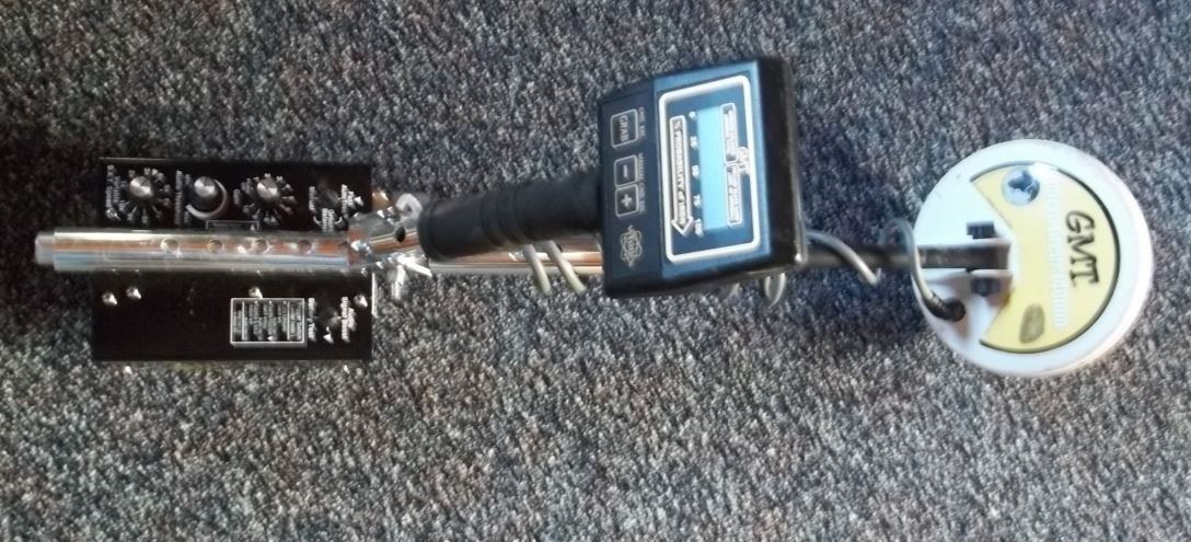
In those days I was detecting in hydraulic pits so it pinpointed a lot of square nails, bullets and junk at pretty good depth as to size. It really helped to find objects in the side of the hole since the larger coils seem to indicate that the target is straight down at the bottom center. Small nuggets around a gram in fine gold mode at a few inches. Larger nuggets could be 4 to 5 inches or more according on size.
-
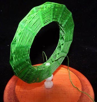
Years ago I had a 3” Diamond Weave wound to the Minelab specification of 300uH by the gentleman below. I put it into a plastic housing with a short handle, similar to the Coiltek coil. I clipped onto the GPX 5000 shaft when not in use. I mounted a small switch box just forward of the detector box that allowed me to toggle from the large mono search coil to this 3” mono pinpointer coil. It worked quite well.
https://www.radiomuseum.org/forum/beautiful_coils.html
-
The guy in the video is new and doesn’t yet understand the proper use of his new detector. He is flailing around too much to get proper response to targets.
Here is more on how it works;
-
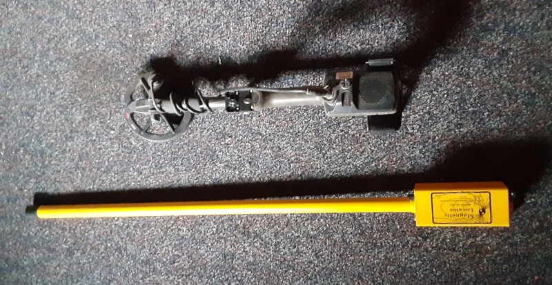
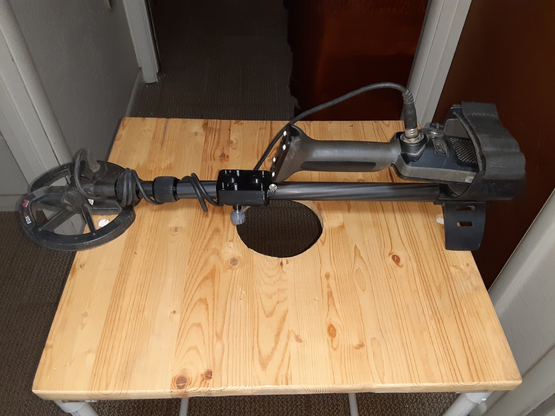
I have had good results with two discrimination detectors. The Equinox 800 is used most of the time. But is not any good on deep targets. But it is very useful for pinpointing and/or discrimination once a big hole is started.
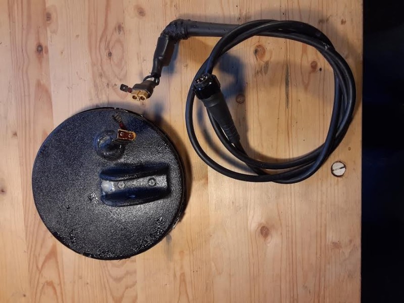
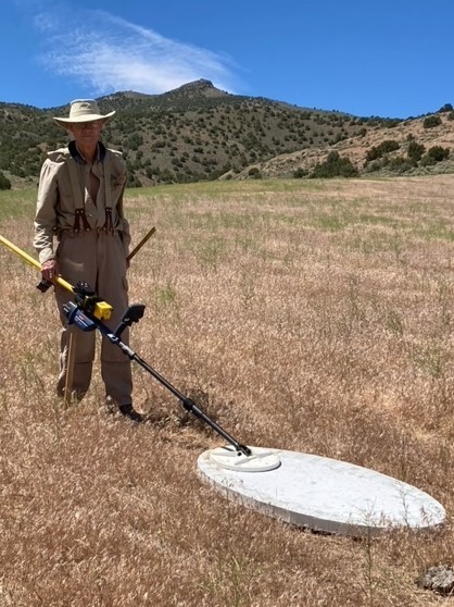
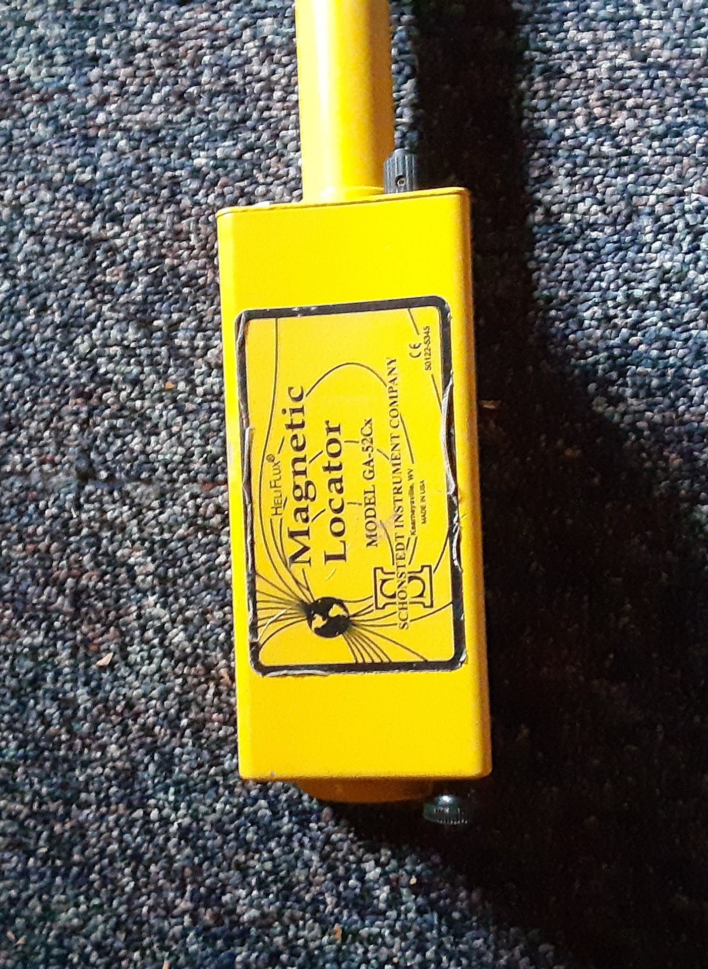
When detecting in the California Hydraulic pits with the GPZ-7000 the Magnetic Locator has been a very dependable discriminator for shallow square nails and DEEP cans and LARGE iron junk. It also does well on some magnetic rocks, the kind that a magnet can grip. Not any good on small trash and wire.
In my opinion three operator selectable modes; Pulse Induction; VLF; and Magnetic Locator technology could be integrated within a single detector. This is feasible with electronic solid state switching to change coil configurations for each mode. The configuration and the sharing of the coil windings and balancing is the most challenging part to accomplish.
-
1 hour ago, klunker said:
So Here's an idea for the jeenyuses. Induction in iron produces a much stronger field than in non-ferrous metals with the same mass. Also iron likes to polarize with the magnetic poles of the planet. Also, as Steve said, we all tend to mentally discriminate targets so why can't computer processing do the same while measuring the strength and polarization of a field?
I'm working on it. Does anyone here have two JJ6LGCC7 vacuum tubes and a 12KV transformer?
Having a Radio and TV business in the 1950s I still have hundreds of vacuum tubes. Even an audio amplifier with 6L6 output tubes. Also a few high voltage transformers are among the collection. What kind of cart or wheelbarrow should we haul this masterpiece on. LOL😄
-
I think it is a quality control problem in the soldering or internal board connections.
The more we gently rapped on it or set it down quickly changed the intermittent nature of the problem. But we could not get it improve or to stay broken.
-
Jason that is the same problem that a friend had. Last year three of us with GPX 6000’s met up for a week of detecting in the Eugene’s off of Jungo Rd.
His detector was new out of the box. It would work and then go crazy just like your detector does. We tried different coils and batteries from the other two detectors. Each combination would work then go crazy again.
Since I had my GPZ 7000 as a backup I used it and let him use my 6000 for the week.
Minelab replaced his detector and the new one works fine.
It’s time to send yours in for a new one.
Chet
-
I have used the GPZ 7000 GPS for 6 years and really appreciate having it built in to the detector.
Prior to the GPZ 7000 when in the wooded mountains and canyons I always carried a hand held GPS.
After I started detecting with the GPZ 7000 I always Set a Waypoint and Start a Track as I left my Jeep. And entered a Find Point for each nugget found. I quit carrying the hand held GPS since the GPZ 7000 was easier and faster to use.
Now with the GPX 6000 I carry my phone loaded with a map application, GAIA GPS. I have loaded it with most of the GPZ 7000 Way Points and Find Points.
-
I just ran an indoor test of my GPX 6000.
Using the supplied Bluetooth connected headphones with max volume.
With room lights including one fluorescent light ON and nearby computer ON the EMI noise with the 11” Mono coil is almost unusable at any settings.
With the 14” Double D coil; Max Sensitivity without Threshold ON it is almost silent; With Threshold ON it has a normal level of EMI noise (similar to the 11” Mono EMI level in open country).
It detected a sub-gram nugget a few inches from the coil with no problem.
My Galaxy A10e phone which I carry with me when detecting (Turned ON) causes no problems when rubbed against the Control Head or the Detector Housing. It is detected as a target when moved over the coil.
It appears that the electronics shielding in my GPX 6000 and the 14” coil cable are working quite well.
Have a good day,
Chet
-
Steve
What an outstanding and complete write-up!👍
Thank you,
Chet
-
My foldable version of the Equinox 800.

-
Most EMI is picked up by the coil. The coil receives EMI similar to the antenna of an AM radio. The larger the coil surface the more EMI is detected. Proper EMI shielding of the coil is the most critical factor.
For a low impedance mono coil the approximate three foot of lead can be a twisted pair of unshielded wires and be very effective in canceling EMI. It does this by the EMI on each wire being balanced and of opposite voltages being introduced by the twisted wires receiving equal and opposing EMI signals.
With a Double D coil the low impedance transmit wires are often a unshielded twisted pair. The higher impedance sensitive receive coil is normally connected by a small diameter shielded cable.
-
The shielding quality and effectiveness of different coil manufactures could explain some of the differences in EMI levels from different coils.
Shielding must provide a critical balance between EMI, Ground effects and best overall detector performance.
Most coils are shielded with a conductive paint which varies in resistance by design and by quality control.
Too low of a resistance paint applied incorrectly will reduce EMI as well as Detector performance.
Too high of a resistance paint will allow more EMI in and more ground noise.
Shielding method and materials used in the approximately three feet of transmit and receive leads is also important to preventing EMI problems.
Some coils may have quality control problems during the manufacturing process.
As with many products performance reports from the users generally sorts out the better products.
Have a good day,
Chet
-
Shortly after I got my GPZ 7000 I tested the WM12 delay and found it to be approximately 20ms which is close to the Garrett Axiom Z-Lynk 17ms delay.
Reference; https://www.detectorprospector.com/forums/topic/2854-testing-the-minelab-pro-sonic-response-time/#comments
Have a good day,
Chet
-
“So just having some fairly decent shallow discrimination on a prospecting machine would be pretty useful in many cases and save a lot of time just being able to concentrate on digging the targets that are higher probability of being gold,“
My preference is to incorporate a separate VLF circuit board or integrated VLF circuity within a Pulse Induction detector with a fast switchover from one mode to the other. The switchover could be as simple as turn off/on the appropriate transmitter. The coil would require special or additional winding/s but is doable. The display and control functions would change with the mode change.
For years when in trashy areas I have carried a modified VLF detector for discriminating and pinpointing. Currently I prefer the Equinox 800.


GPZ 7000 Tear-down
in Minelab Metal Detectors
Posted
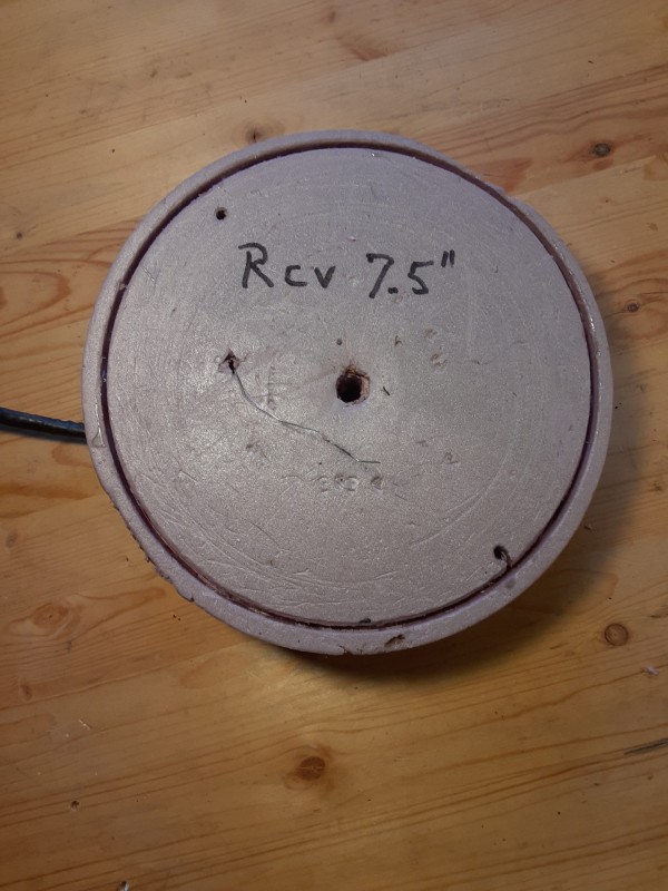
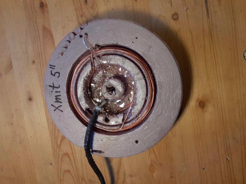
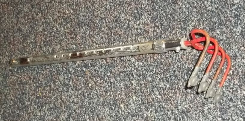
The majority of pulse inductance detectors are designed to operate with coils that have an inductance of 300 microhenries with a resistance of less than 0.5 ohms and less than 400 picofarads of coil and lead capacitance. A small coil requires almost as many feet of heavy gauge wire as a large coil to meet required specifications. This means that the small coil space severely limits winding forms. My six inch GPX 6000 mono coil (below) required two flat wound layers which fill up the housing. The eight inch GPZ 7000 concentric coil (also below) was accomplished by stacking the windings vertically which doubled the height of the coil.
A coil lead is approximately 50 to 100 picofarads which is considerably less than normal coil capacitance. Moving the receiver or preamplifier into a pulse induction coil is more of a problem than with a VLF detector. It would also make aftermarket coils very difficult and expensive.
The GPX 6000 coils are very sensitive to small and tiny nuggets. There is more to gain in signal and EMI processing than in coil design.