Chet
-
Posts
211 -
Joined
-
Last visited
-
Days Won
1
2 Followers
.thumb.JPG.b46839319dc8de4aefe1f42407094dbd.JPG)

Recent Profile Visitors
3,266 profile views


Chet's Achievements
")
Silver Contributor (4/6)
813
Reputation
-

Stacked Spiral Coil Windings
Chet replied to RONS DETECTORS MINELAB's topic in Detector Prospector Forum
The most deciding factor appears to be the smaller the center hole the more concentrated and stronger the magnetic force is across the coil face and through the center. I have built a few porotype coils modeled after different MRI coils and even modeled an airborne coil that is used for detecting oil pools trapped under the arctic ice. It used the earth’s magnetic field instead of a transmitter. Sadly they didn’t work very well for metal detecting. Some of the high energy coils used in nuclear fusion power experiments are appealing but scaled down are still just not practical for small light weight coils. -
Stacked Spiral Coil Windings
Chet replied to RONS DETECTORS MINELAB's topic in Detector Prospector Forum
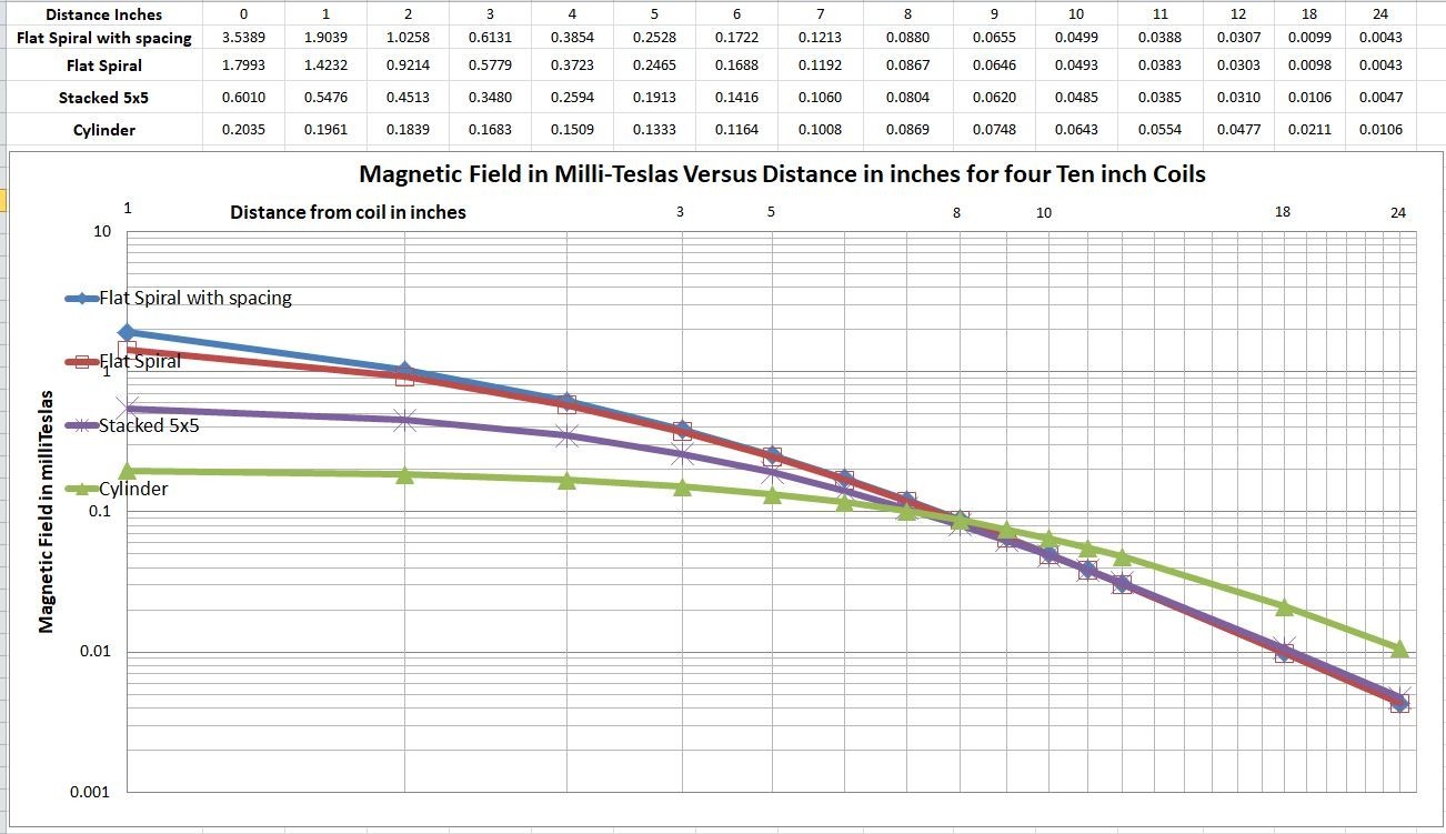
I have over the years built a few detectors and a large number of coils of all sizes and configurations. I have spent many hours with oscilloscopes and test equipment looking at results of the different timings and settings of the GPX 5000 with different coils and different target sizes. I have generated a lot of Excel spreadsheets in the process. Some of what I have learned is that the best coils are constructed with Litz wire which reduces skin effect losses. Coils should have an overall coil resistance of less than 0.5 ohms. This is important to ensure enough current flow has occurred to fully magnetize the coil before discharging it. Otherwise it will result in a weaker transmit magnetic field. High coil frequency response is required to sample for the smallest nuggets right after the pulsed magnetic field collapses. To accomplish this the coil is constructed in a manner that reduces stray capacitance and when possible low proximity effect losses between adjacent windings. Spiral windings are a partial solution to reducing stray capacitance and proximity effect losses and providing a high frequency response. The magnetic field pattern/lines of force around an air core coil are pretty much the same whether it is AC or DC or Pulsed currents. In order to save time I now rely on online calculators to simplify the process and design of coils. I used the online calculator below to generate each one-inch magnetic value for input data to the previous Excel chart. https://www.accelinstruments.com/Magnetic/Magnetic-field-calculator.html -
Stacked Spiral Coil Windings
Chet replied to RONS DETECTORS MINELAB's topic in Detector Prospector Forum
Flat Spiral Wound Coils increase and concentrate the magnetic field near to the coil. The following four ten inch coils are designed with 2 mm Litz wire with number of turns needed to approximately meet the industry standard inductance of 300 microhenrys (uH). The flat spiral coil has 43 turns in a 3.39” band that leaves a 3.23” diameter center hole. There is another flat spiral coil that has 0.1 mm spacing between turns. It has 55 turns that leaves a 1” diameter center hole. The 5x5 stacked coil has 24 turns in a 0.4” square band that leaves a 9.2” diameter center hole. The cylinder coil has 16.5 vertical stacked turns in a 0.2” band that leaves a 9.8” diameter center hole. The magnetic unit of Tesla or milliteslas (mT) is named after Nikola Tesla. Examples are (5 mT) – the strength of a typical refrigerator magnet; (.05 mT) – the strength of the earth’s magnetic field on a compass. The attached chart shows that the magnetic field of spiral wound coils is strongest close to the coil and concentrates through the center hole of the flat windings. This provides exceptional results on small nuggets and sharp pinpointing within the center hole of the coil windings. Click on chart to expand it.
- 19 replies
-
- 10
-

-

-
开元通宝 ! 唐朝钱币 Kaiyuan Tongbao! Tang Dynasty coins
-
I have sent you a PM.
-
It does not change the inductance. It acts as an active fixed circuit capacitance that reduces outside variable capacitances caused by changes in height and conductivity of the soil as the coil moves over it. If the shield is too close to the windings it can add considerable capacitance to the circuit which lowers the frequency response and response to smaller nuggets. I try to space it around 0.25 inches with a graphite resistance of around 100 ohms per inch. I have seen some Minelab coils be as low as 50 ohms per inch. If you go that low I recommend a long thin unpainted gap to prevent a circular short circuit. The gap should start top center, across, down, back across the bottom to center. On size; I shield the entire coil. Large coils could be shielded around the winding areas with satisfactory results. Metallic conductive spray paints can be a problem and should not be used for metal detector shields.
-
I also have one of the early 10” X-coils which I also heated and wrapped for tighter turns. Later I opened the plastic housing up with the intent to replace the cable. It was not practical if not impossible. I recommend replacing it with a new cable. Making the splice midway between the coil and the curly part of the cable. Use marine grade (has hot glue inside) shrink tubing over each splice and over the entire area. Phrunt put me onto this source for cables. I have ordered both the GPZ 7000 and the GPX 6000 cables. I will let you know the quality when they arrive. Applicable to metal detector: gpz7000 sdc2300 gold monster 1000 (aliexpress.com)
-
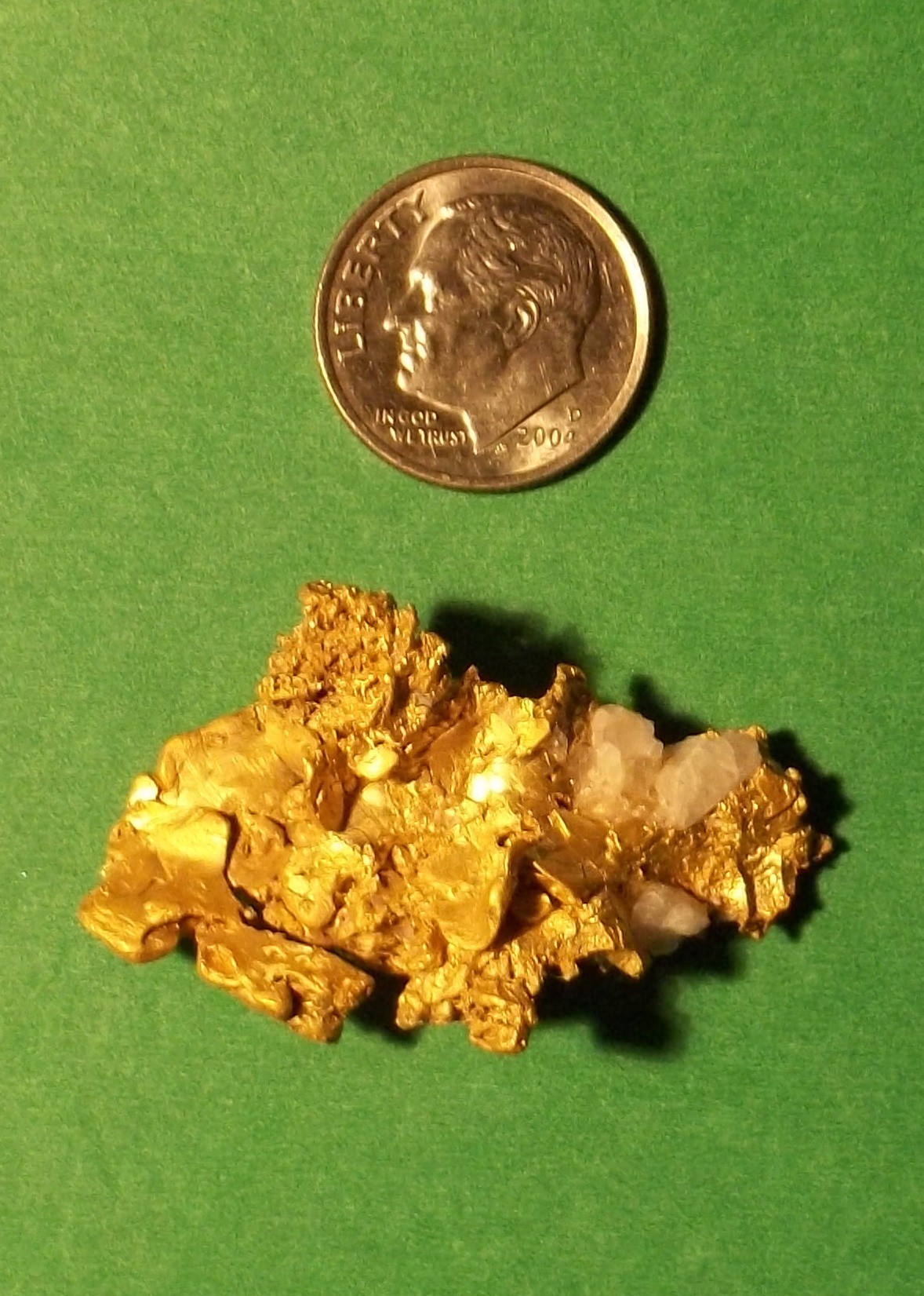
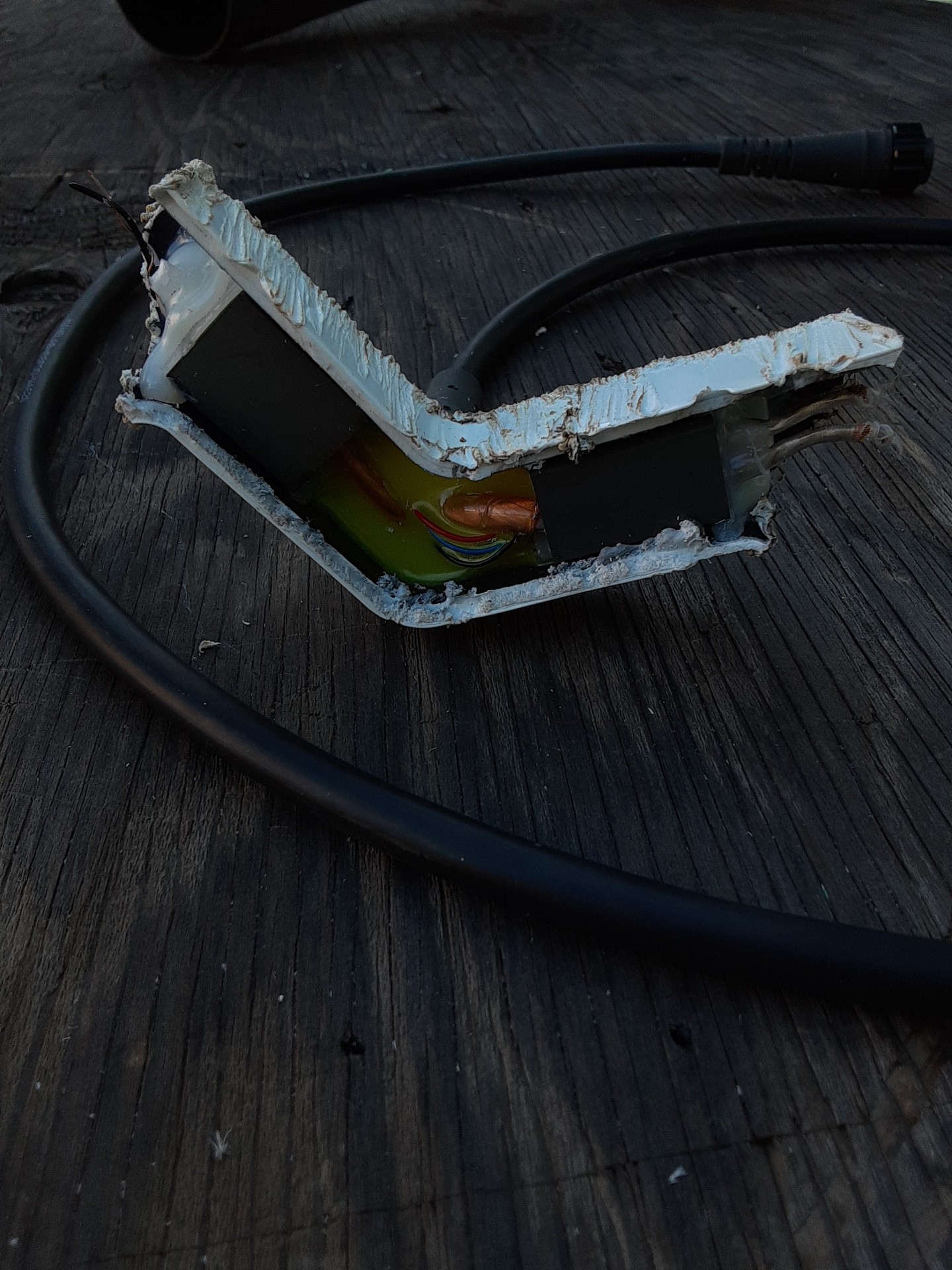
Over the years I have repaired several coils with dried out masking tape and a couple of dried out carbon sponges. I will relate on of my experiences with one coil while detecting in a new undisturbed gully. Detected and dug a few square nails then the detector goes crazy making all kinds of noise. With more than 60 years of electronics experience I know how to fix most problems. Turn it off and back on; several cycles later go to plan B; tap it gently; after banging it into rocks and trees; give up and have lunch on a big flat rock. Since we car pool going home early isn’t an option. From the previous scientific diagnostic testing (remember the banging of the coil test) it was determined that the problem was inside of the coil. Probably getting revenge for allowing myself and it to slide and crash into a gully the previous week. And there is no spare coil available; it’s time for another plan. A Pulse Induction Mono coil is a simple three wire circuit inside of a sealed waterproof plastic shell. So simple even that MacGyver TV guy could handle this. Have you ever seen someone whetstone their prize Buck Knife until they can shave with it. Well it’s that time to put it to work. Working on my leg-top workbench I peeled off the tape that holds the skid plate to the coil housing. Then with my razor sharp Buck Knife cut and pried through the sealed plastic seam around the perimeter of the coil. Spliced the broken shield wire and secured it with a piece of the skid plate tape. Closed it up and secured it with the remaining tape. At this point I realized that I hadn’t stabbed my leg or cut a single finger! Now for the test; turned it on and it purred like a kitten; went about 10ft and got a soft nice sounding target. Dug down about 10” and came up with a beautiful 13.8 dwt / 21.5 grams nugget! Some days it's just written in the stars.

-
Yes, the other end is embeded into the graphite paint. Better than painters tape LOL.
-
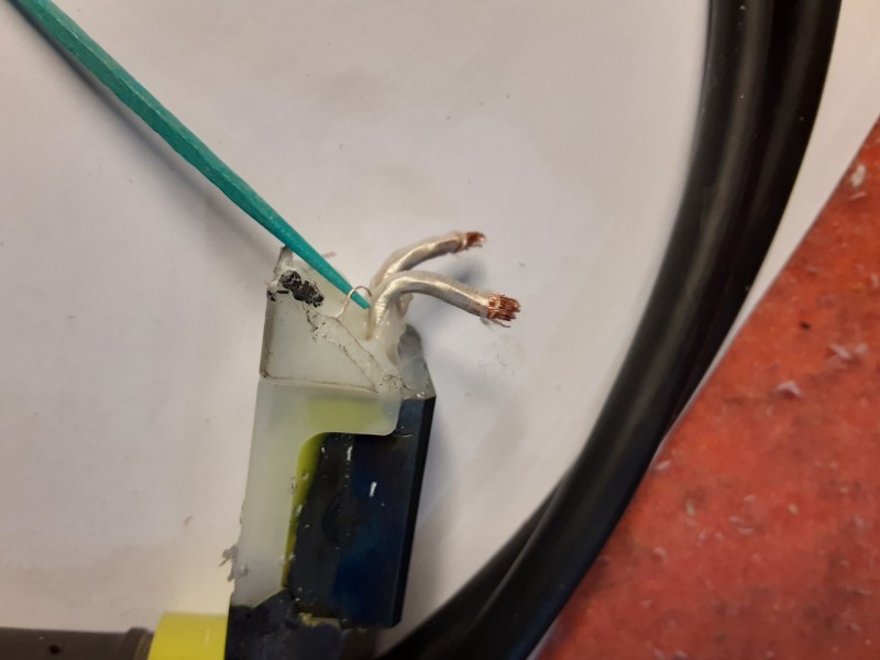
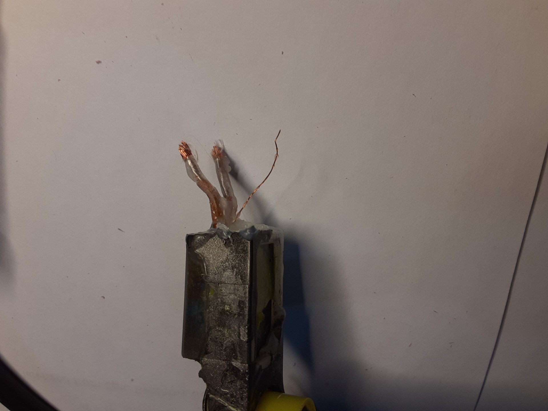
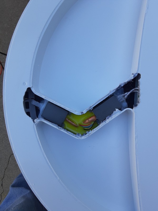
Yes, this was a factory defect. Yes, the GPX 6000 screen wire is wired differently. It is carried on separate/isolated wire within the coil cable and terminated on the printed circuit board within the control box. The standard GPX 5000 Mono coil uses a single coax cable with a single transmit/receive wire inside a braided coax shield. Inside the coil housing the graphite coil shield drain wire is soldered to the braided coax shield. Most GPX 5000 Double D coils use two coax cables one for a D shaped transmit/receive coil, the other for a D shaped receive coil with a single wire inside each braided coax shield. The transmit coax shield is required since the GPX 5000 uses the transmit coil as an additional receive coil when a Double D coil is used in Mono or Cancel modes. Inside the coil housing the graphite coil shield drain wire is normally soldered to the receiver braided coax shield. In some incidents this drain wire to coax shield connection is done with a jumper wire inside the five pin cable connector. In summation the GPX 6000 graphite coil shielding requires an isolated ground/drain wire. Standard GPX 5000 coils cannot be easily adapted to the GPX 6000 because the ground/drain wire is internally connected to a cable coax shield. Also the GPX 6000 appears to be finicky if the shielding, inductance, capacitance and resistance of the coils are not just right. Attached photo shows the drain wire after I heated up the plastic and pulled out the loose end. Inside the coil housing I can see where it was broken from the graphite shield.

-
Not for us coil winders.lol But you are right for standard available coils.
-
I think I found the problem with the GPX 6000 not working well with the 5000 and 7000 coils. The 6000 14” DD receiver coil measures 300uH, 4.0 ohms. The other 5000 DD and 7000 DOD receiver coils measure more than 400uH and much higher resistances. This indicates that the GPX 6000 DD coil has fewer receiver coil wire turns than the other DD coils. The GPX 6000 GeoSense function/operation probably needs close to 300uH for both mono and DD modes.
-
Thank you this source will help a lot on some of my projects.
-
The chip is embedded in epoxy so I am worried about damaging it with heat and/or tools to remove it. I don't want to sacrifice another coil if I mess-up. And additional coil cable for additional coils is hard to come by.

-
If you look closely at the photo with the green toothpick; the bare wire that is looped back into the white plastic goop is the shield/ground wire. It should have been connected to the graphite shield inside the coil housing. They may have had a new employee or some accident in assembly of the coil? It resulted in a noisy and ground sensitive coil.