bklein
-
Posts
435 -
Joined
-
Last visited
Content Type
Forums
Detector Prospector Home
Detector Database
Downloads
Posts posted by bklein
-
-
I took off the rear of the connector and maybe it was put on too tight and caused a compression short? That and I sprayed the pins with Dr-Oxit. Works now.
-
It is possible to make a cable that connects the control head to the pod placed on your waist. You’d still need the Minelab harness though to hold the weight. Your swing mass would be less so better on the right arm tendons.
-
I would think there would be a positive, negative, and shield. The shield would contact the ground somewhere but if not attached to the loose pin it would allow more EMI. Preliminary ohmmeter tests were ok both coils.
-
I have a Trifield meter which senses various interferences. I took it around the house and found an area behind my house that has a minimum measurement. Wasn’t really that bad in the garage though so maybe it’s meaningless (2.1 vs 2.3mg weighted mode, it’s 2.9mg right now at 7:40PST). If you have read my other thread though you will see my 12.5” coil died on All Metal so I need to fix that tomorrow morning.
I added the video of the 12.5” coil failure behavior to the thread.
-
Turned it on and All Metal mode was dead, Tone mode works, 12.5” coil. Tried8” coil and it works on both. Will show video later. Looked at connector pins and see some loose ones. Is this ok?
-
I’m kinda hoping one of you take the reigns and test in your garage and then the local park to prove your theory.... 🙂 I have an upstairs rear deck that might work. It has metal sheeting and chicken wire embedded in the floor. The power wiring for our area is underground, under the sidewalk in the front of the house.
-
I have, did that first but video of it was terrible. Results were the same. I’ve seen French videos of guys getting 16” in their work areas…
-
EMI rejection seems to have an issue when moving from All Metal to Tone mode.
[Major Edit] I removed two videos that were testing in my garage with too much EMI. Better depth discussions later.
-
see other thread for updated video.
-
Yes I was using his 19” video as a hopeful reference. He got a little less with the horizontal air test.
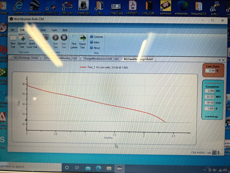
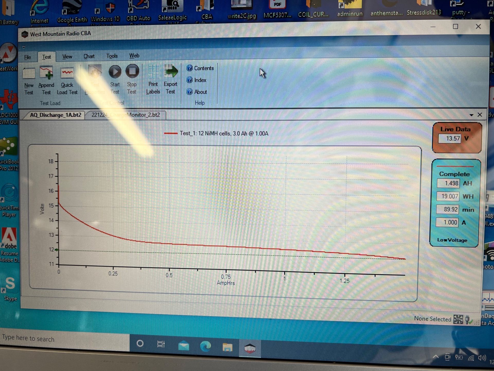
Attached is a photo of the discharge curve of my 14.8V OBN li-ion pack.
-
Here is a 1 amp discharge graph I took of the stock battery right after charging it. It starts out close to 16.5 volts but drops to 15.5 volts or so right as load is applied and runs most of the duration around 12.5volts. The detector would have to have a boost converter to maintain TX source voltage at 15V. I need to make up a test cable attached to a bench supply to test the detector voltage range and behavior.
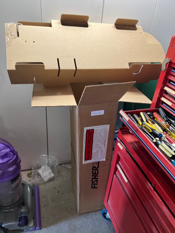
As far as sending the unit I left out the coil shaft and battery per their instructions. They send the unit back in an elaborate cardboard structure inside the box (see photo). Shipping cost is highly dependent on the box size so try for compact if you can.
-
I tried my detector with the stock battery pack, which I had charged last week. I was still only getting about 11” on a nickel. I checked the battery voltage though and it is 14.1V. The OBN pack is 14.77V. Could you guys advise if you can get 16” on a nickel and if so what your battery voltage is?
-
I went ahead and used the pill bottle, cut in half, on two coils. I kept the wires straight and used the Heyco you show. I used heat shrink on each individual wire, then wrapped with electrical tape, slipped the pill bottle over it. I used hot melt to temporarily seal the bottle to the coil base, and poured in the resin. Seems fine.
-
CJC, could you post some photos of the wobbly shaft issue? Mine came back from Fisher without this being addressed. I baby it so maybe it’s a non-issue for now(?) Maybe all are like mine out of the factory?
-
I received my detector and they didn’t find any wrong with it - NTF. They watched my videos of testing the delay switch. Oh well.
-
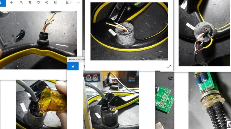
I’m not really understanding the purpose of the cut off portion screwed on to the base coil connection (top left photo). It says it is so the resin locks in to it but it would do that without it too. It seems the technique is to add a stress relief base offset from the original. The piece that sticks out though has me questioning though - it doesn’t seem to have anything for the resin to hold on to. I think there used to be your videos on this whole process but I can’t find them anymore. I guess there isn’t something that would screw to the coil base and contain the cable connections. Seems wrong thread on everything.
I was going to use a pill bottle for the plastic cylinder but now worry that it may be polypropylene and not bond to the coil housing or epoxy resin - probably better to find something else eh? -
They fixed the Delay switch at a minimum.
-
My detector was repaired and is on its way back to me!
No word of cost so I'm not complaining!
-
It has always been practice to minimize detectable materials in detection range. It would be good to see someone run target depth tests with different shaft types.
-
Can the detector sense carbon fiber like my Carrot pinpointer can? Maybe fiberglass is better?
-
I just managed to get in touch with a human (Gabby) in customer service and she’ll call me back with a status. One of the issues it has is this wobbly mount.
-
My detectors are both built from parts. They have inline connectors so I can swap coils. Both have a Mogami brand cabling with two pair blue and clear wires. I can’t visually tell what’s paired. I can determine TX and RX pairs though with my multimeter. TX are low resistance, RX higher - like 1.1K. If I take the control head apart I can tell what goes where but I am trying to avoid that as due to my pot shaft adapters it’s really hard to get all to line up on reassembly.
Are you suggesting if I don’t hear the pliers it is wired wrong? So fix that by TX wire swap then test for target centering and swap RX wires if wrong? Go back to TX with the pliers and verify heard in all metal minimum discrimination.
I’m confused as you say normal Excal behavior is to mask out the pliers (like my friend’s stock unit). -
9 minutes ago, Joe Beechnut OBN said:
Now the question is, the other excalibur..why it does not do the same.
Your mis-wiring YouTube video shows the detector sounding on the needle nose pliers. That’s why I was testing them.
-
One of my two Excals blanks out the pair of needle nose pliers. (Discriminate set to minimum) Any idea what might cause this? Wrong value pot? Jeez I hate to open it up again.
Edit: I just borrowed my friend’s stock Excal II and it also discs out the pliers in min Disc setting.


AQ Impulse, Depth Testing, Emi Rejection Issue
in First Texas - Bounty Hunter, Fisher & Teknetics
Posted
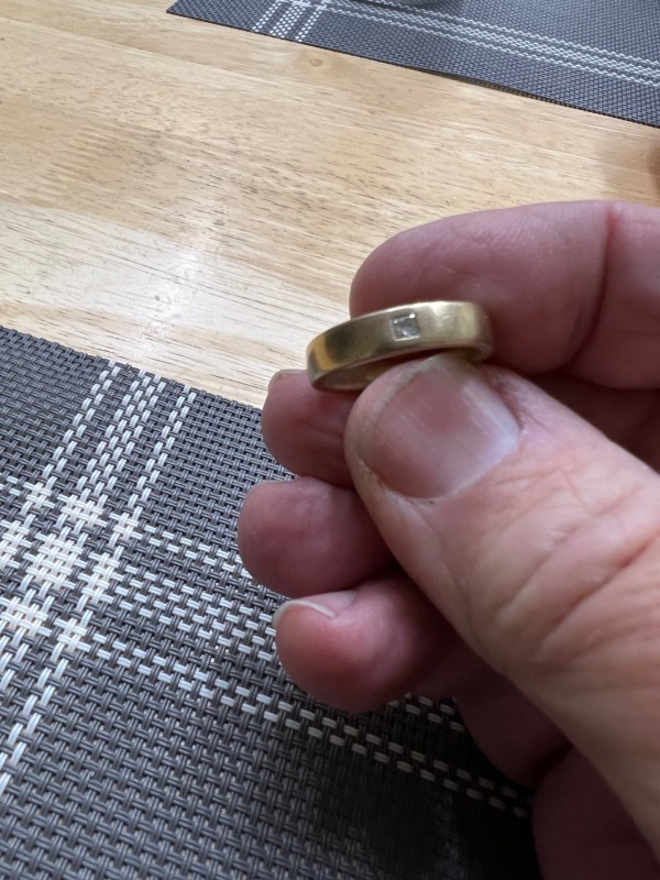
The gold ring is 18K, 17.77mm ID (I don’t have a ring sizer), 8.6g and has a diamond.