


steveg
-
Posts
1,207 -
Joined
-
Last visited
Content Type
Forums
Detector Prospector Home
Detector Database
Downloads
Posts posted by steveg
-
-
20 hours ago, GB_Amateur said:
Yep, all good, Steve. I didn't mean to counter what you said but rather enhance it. And since I've never used an FBS detector I was hoping to get a confirmation, which you gave (thank you for that). Possibly I should have been more careful/explicit in my post -- next time....

GB -- OH MY! I am sorry if something I said, or the way I said it, caused you in any way to feel you had to apologize in any way! I guess I didn't use enough emojis or whatever!
I simply thought, from your response, that maybe my post was suggesting that I didn't think target trace could be a useful tool, so I wanted to clarify that my post was more narrow, in terms of what I was saying that target trace might not help a whole lot with.
It's all good, and CERTAINLY no need to apologize in any way! In fact, I offer you MY apology, if that's what my post suggested to you! By all means (and this should go without saying, but...) feel free to counter ANYTHING I say, any time you feel it necessary! I'm always up for a good point/counterpoint discussion!
Steve -
I am wondering if the mixed audio will be like running both "conductive tones" and "ferrous tones," as you could on the Explorers and E-Trac, but AT THE SAME TIME (one in either ear). Now THAT could be interesting...
Steve -
strick --
Don't think it is a bar chart or histogram. I believe it to be an x,y coordinate system, very similar to the CTX 2-D smart screen, but we shall see.
Steve -
3 hours ago, GB_Amateur said:
Suppose you have a target that is giving multiple dTID's, but there is a clustering around a particular (conductive) value. E.g. 22,25,26,29,26,25,25,24. That may be difficult for the human brain to decipher, but a plot (even one dimensional) should indicate there is a peak at 25-26 in this example, and especially if more datapoints are integrated in the X-Y plot.
I appreciate your explanations, being one (of many) who has never used an FBS detector. But "a picture is worth a thousand words" and "a plot is worth a thousand numbers".
GB_Amateur --
ABSOLUTELY. I agree with you. I was NOT saying, by any stretch, that target trace isn't in any way helpful. ABSOLUTELY what you said is true -- all those IDs, plotted in a visual format, clustered around an "average" value, certainly does offer help for dig/no-dig decisions.
Recall, all of that extremely long and involved explanation that I "vomited" onto the thread, was typed SPECIFICALLY in response to this statement...
"Well for one thing if the 2-d screen works as advertised falsing iron targets should become obvious without circling targets. "And so, I was simply trying to explain why having a 2-D screen IN AND OF ITSELF won't "make iron targets obvious without circling," if the nail is at all "falsy"...
Steve -
longbow,
Yes, that is correct. You probably did see that. But, the KEY, and the CAVEAT, is THIS -- the targets (if you want their traces to show up in their "proper" places on the 2D screen) must be identified correctly by the machine's ID algorithms, in order for them to show up in the proper place on the screen.
Consider four scenarios...
Scenario 1, you are using a CTX, and you have both a nail and a coin, sitting adjacent to one another. And let's assume that the nail is IDing ENTIRELY as a nail -- i.e. the machine correctly identifies it as an ENTIRELY iron target, and reports it entirely with iron ID. And let's also assume that the machine is correctly, solidly IDing the coin as a high conductor. In that case, then what you said is correct. You will see two targets -- a round-ish target on the center line (the coin), and a more "oddly shaped" or "smeared" target in the "iron area" of the screen (the nail).
Scenario 2, you are using a CTX and you have both a nail and a coin, sitting adjacent to one another. And let's assume that the nail is IDing PARTLY as iron, but PARTLY as a high conductor (i.e. you are hearing a mix of high tones and iron tones). And let's also assume that the machine is correctly, solidly IDing the coin as a high conductor. In THIS case, you would probably see some semblance of THREE targets -- the coin, on the center line, and then one trace clustered up in the "iron area" (representing the sweeps of the coil where the machine is correctly IDing the nail as "iron"), and then another trace clustered near the center line (somewhere in the vicinity of the coin's trace) that is representing the sweeps of the coil where the machine was reporting the nail as a high conductor.
Scenario 3, you are using a CTX and you have ONLY a nail under the coil, and the nail is being ID'd ENTIRELY as a nail -- no high-tone falses. In this case, you will see a single, somewhat non-round target or "smeared" trace in the "iron area" of the 2D screen.
Scenario 4, you are using a CTX and you have ONLY a nail under the coil, but the nail is IDing PARTLY as iron, but PARTLY as a high conductor. (i.e. you are hearing a mix of high tones and iron tones). In THIS case, you would see some semblance of TWO targets -- one trace clustered up in the "iron area" (representing the sweeps of the coil where the machine is correctly IDing the nail as "iron"), and then another trace clustered near the center line that is representing the sweeps of the coil where the machine was incorrectly reporting the nail as a high conductor.
Does this make sense? In reality, what you would see is more complex, especially in scenario 3 and 4. Reason being, we all know that the ID of a rusty nail "jumps around" alot; even if not into the high tone range at times, the ID still "jumps around." Well, this "jumping around" of the ID corresponds to the "smeared" target trace you mentioned in your post.
The important thing to keep in mind, to understand target trace, is this (assuming the M-Core target trace works essentially the same as the CTX)...
...all that target trace is, is a visual plot of what your ears are hearing (again, this is assuming that the M-Core target trace is very similar to the CTX target trace, and I feel reasonably confident that it is).
Each ID of your target, on the CTX, and also on the M-Core, is broken into a conductive number, and a ferrous number. On the M-Core screen, you are ONLY seeing the conductive number; on the CTX and other FBS units you see both numbers (except on the Safari, where you only see the conductive number, but I digress). Anyway, the point is, in the BACKGROUND of the M-Core, both numbers are being calculated. And so, let's say a quarter IDs on M-Core as "90." That's the CONDUCTIVE number. But, there is a Ferrous number also being calculated -- so let's just call it "12." So, in the background, the quarter is IDing as 12-90. And so, if you think of the 2D screen as simply an x,y coordinate system, with conductive ID being the x-axis, and ferrous ID being the y-axis, then that quarter's 12-90 ID is simply an x,y coordinate pair, that can now be plotted on an x,y coordinate system -- and again, that's what the "2D screen" is. So, if you plot your ID point in the location that corresponds to 12 on your y-axis, and 90 on your x-axis, you have just plotted the quarter, on the 2D screen. And as you continue to pass the coil over your quarter, and get more 12-90 ID's, your machine will continue to add more 12-90 points on the 2D screen. If you get a slight variance of the ID on some sweeps (which of course you do), i.e. you get an 11-90, or a 12-91 ID, on some sweeps, those will plot, also. That's why the trace "grows" a bit, with time, the more sweeps of the coil you make.
SO -- a target that is ID'd accurately by the machine, with little variance in ID from sweep to sweep, will produce a small target trace; meanwhile, a target -- like a nail -- that IDs kind of "all over the place," will make a SMEARED target trace. Again, the important thing to keep in mind is that all the target trace shows, are each of the ID "readings" that the machine is taking, of the target you are sweeping, plotted on the 2D screen (the x,y coordinate system).
AND SO -- to sum this all up, the only way (assuming I am right about the M-Core and CTX target traces being very similar) that you will see the nail SOLIDLY in the "iron" area of the screen, consistently and entirely, is IF THE MACHINE IS CONSISTENTLY AND ENTIRELY ID-ing THE NAIL AS IRON. If however, the machine erroneously reports, on some sweeps, a "coin-like" ID for the nail, then that "coin-like" ID will be shown in a "coin-type" location on the 2D screen. And hence, the nail would show up as kind of "two targets" -- one clustering of IDs in a "coin-type" location, and one clustering of IDs in an "iron-type" location, due to some sweeps IDing the nail as iron, and some sweeps IDing it as a high conductor.
Hopefully, this makes sense; sorry about the wordiness, but if you have never experienced a FE-CO target ID, and a "smart screen," then it's a concept that takes some getting used to, and I don't know of a succinct, non-wordy way to describe it. My apologies.
Steve -
7 hours ago, strick said:
That looks very cool Steve...Are you going to do a strait shaft as well?
strick
Strick,
I hadn't planned to do so, and hadn't really thought about it at this point. But just giving it some preliminary thought here, it might be possible to do so, using my handle. If there was someone that wanted a straight shaft, I could certainly see what could be done...
Thanks!
Steve -
6 hours ago, CPT_GhostLight said:
That's awesome, Steve!
Thank you, CPT!
Steve -
6 hours ago, Brad Plohman said:
Looks good Steve!
Thanks, Brad!
-
On 10/9/2022 at 5:19 PM, longbow62 said:
Well for one thing if the 2-d screen works as advertised falsing iron targets should become obvious without circling targets.
I wouldn't count on that. My experience with the CTX says that if you have a nail that is a mix of iron tones, and also a bunch of high-tone "falses" that somewhat mimic a coin-type target. you will get a trace for both of those tonal indications. In other words, the target trace would be such that it would look kind of like there are two targets under your coil -- iron target, and coin-type target. Reason being, if the ID algorithms are "fooled" into giving you a coin-like high-tone, then (at least with the CTX) the target trace algorithm is likewise fooled. I don't think you can expect to be hearing both high tones and iron tones, but ONLY see an iron trace on the 2D screen.
Unless they have some real magic going on with the Manticore that STOPS the nails from high-tone falsing, then I would expect any high-tone falses to "trace" on the target trace screen along the "good target" line (in addition to the trace in the iron range consistent with the iron tones that would be occurring due to it being an iron target).Steve
-
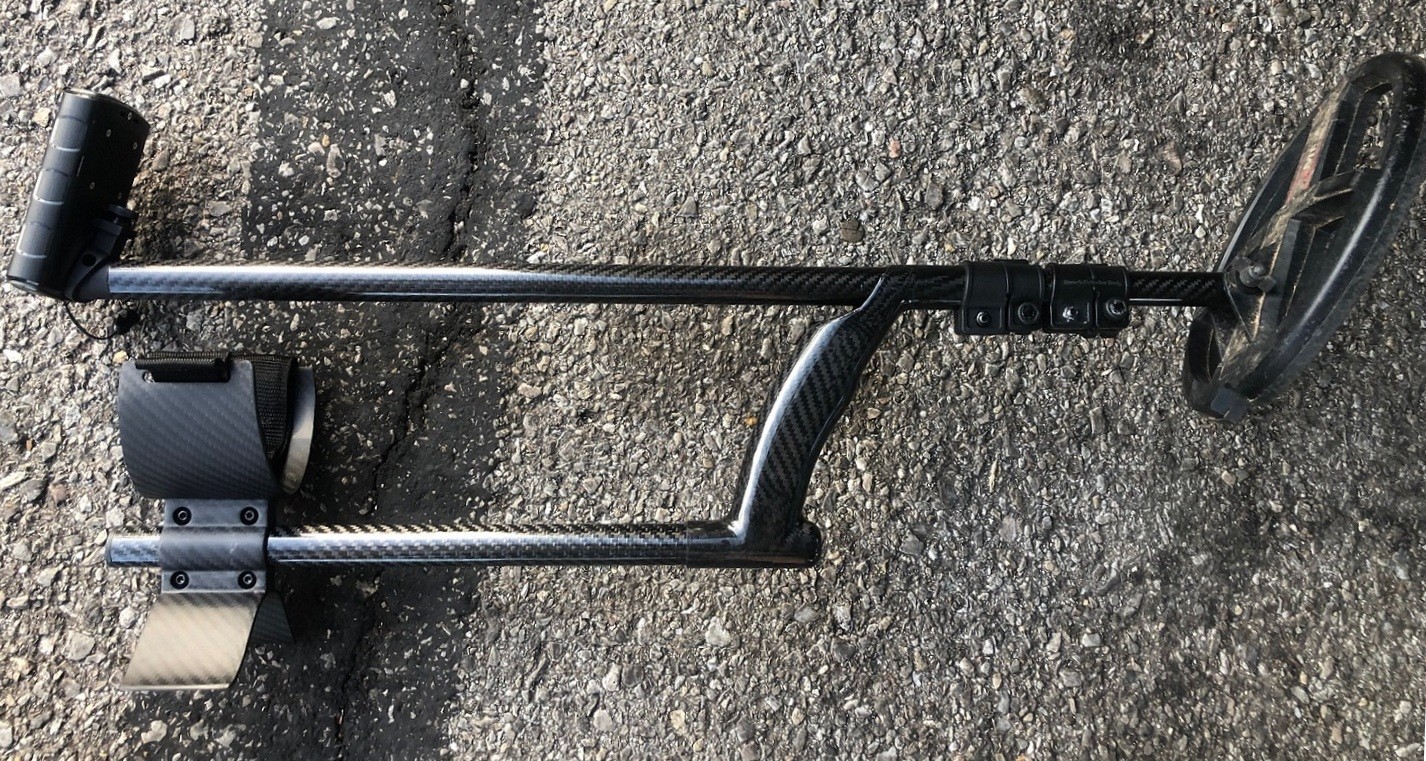
Locking mount for the remote control now being tested (see picture)
Steve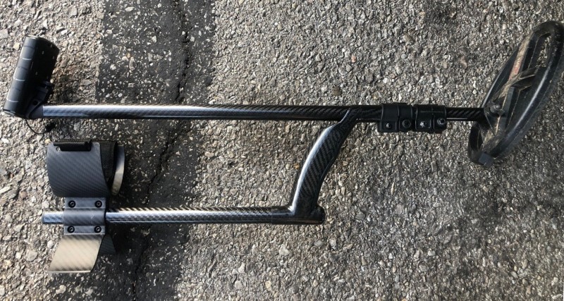
-
martygene -- yup, I have you on the "informal" list also! 😉
-
Thanks! 🙂
Steve -
Hi all!
I am making good progress on the D2 shaft project. The last loose end is the remote-control mount. The one that was tested by my field testers was a non-locking version, similar to the one that is on the stock shaft. However, over the past couple of months I've been working to revise the design to include a locking mechanism on the mount. That revised design has been completed, and I have a few 3D-printed samples of this new locking version of the mount en route to me. I need to test these new mounts to be sure the dimensions are correct, and that the locking mechanism works as intended.
As soon as testing on the locking mount is complete (I expect that it won't take long), and assuming it works as intended with no design tweaks needed, then I will initiate production of the injection mold needed to produce the new mounts. Usually, it takes about 4 weeks to produce a mold, and then I'll immediately have the first batch of those mounts produced with the new mold. Production of injection-molded parts only takes a couple of days, and then they can be shipped to me. All other parts for the first production run of shafts have been ordered -- some I have already received, and some remain in production, with receipt expected in 3 to 4 weeks. So, it's just the mounts that are the delay at this point. As soon as I receive them, I'll begin producing -- and shipping -- the first run of shafts to customers.
I already have a large number of names on an informal "wait list," but will be setting up a "formal" wait list as soon as I confirm that the 3D test mounts are proper, and have begun production on the necessary injection mold.
Thanks everyone, for your patience!
Steve
-
Wheeler,
Thanks for your reply. So far, the field testers have found the grip to be quite comfortable; my thought is that if anyone wants anything rubbery or padded, it can be added via "grip tape" or other similar options (such as used with sporting equipment, etc.) I use a "fishing rod grip wrap" on my Equinox, and really like it.
Unfortunately, my lower rods will not be compatible with the stock shaft. The XP shaft uses "trapezoidal" tubes, and mine uses round tubes, so the two are not compatible. My apologies on that...
Thank you!
Steve -
12 hours ago, midalake said:
I have beach hunted for 25 years in the worst conditions that the Pacific Ocean can dish out. I have NEVER broken a lower carbon fiber stem or coil attachment yoke.
To add to this, I've never had a one of my shaft users report a broken shaft while ocean detecting, and I have LOTS of dedicated beach hunters using my shafts in the surf...
Carbon fiber -- given its strength-to-weight ratio and the fact that it won't rust/corrode/deteriorate -- should be among the very BEST materials to use, for a shaft -- whether dry land hunting, OR beach/surf hunting...
Steve
-
5 hours ago, CPT_GhostLight said:
Wow, that's dead sexy, Steve! 😎👍
Thank you! 🙂
Steve -
6 hours ago, F350Platinum said:
Looks nice Steve.
Locking mechanism for remote?
It's being worked on as we speak; the measurements/specs are in the hands of my producer now, and they are working on the drawing...
Thanks!
Steve -
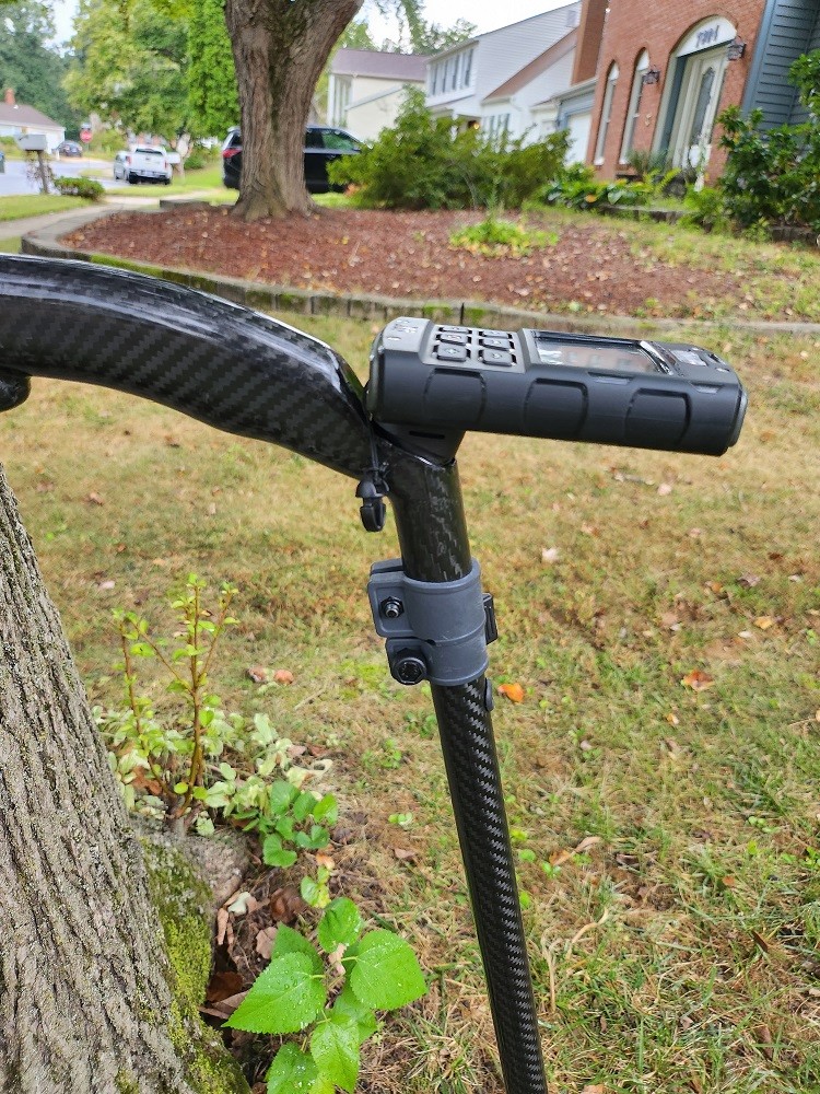
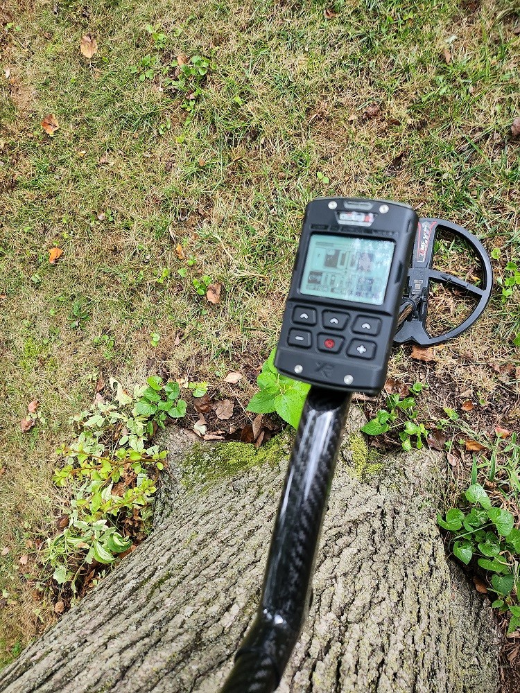
A few pics from one of the field testers...
Steve


-
A bit late, but wanted to thank everyone who chimed into answer some of my questions about PI vs. VLF, time domain and frequency domain, etc.
I am on a vacation now, and so little time to post, but I've been reading all replies and I greatly appreciate the time taken to help further my understanding...
A sincere thank you!
Steve -
16 hours ago, Geotech said:
It's a fairly complicated topic that really requires a whole book chapter and a lot of diagrams to explain*. In the old days all VLF designs were frequency domain (or, more accurately, phase domain) and all PI designs were time domain. But BBS/FBS/FBS2 (all really the same basic tech) created sequentially-transmitted frequencies where freq-domain processing doesn't work because the dead time between frequencies would screw up the channel filters. So ML used time-domain processing which, honestly, looks somewhat similar to normal freq-domain sampling. But it's done on ramped-exponential decays instead of sinusoids. From the time-domain sampling you can still get the equivalent of a target phase.
PI is also time-domain (and always will be) and also samples a decaying exponential but it does so during a TX "quiet time" where the TX signal is not changing. With FBS the TX signal is always changing, just like VLF. And with PI, you can never extract a target phase.
This was a good differentiator until the GPZ came along. In traditional PI the TX current is turned completely off during the RX sampling. In the GPZ it is not, but it is also not changing (the TX current is a bipolar square wave) so the result is exactly the same: there is no changing TX field during RX sampling. So now my definition of PI is a system that receives during a TX dead time, whether current is zero or a DC value. Put another way, during sampling there is no reactive signal.
*Inside the Metal Detector, 3rd ed, Ch 2; pub. 2023 (I hope)
Carl and Steve
THANKS for the further information. VERY good stuff. Steve, I know you explained alot of this to me, before, but it's challenging information, so please excuse me that you had to repeat yourself, again! And Carl, I'll look forward VERY much to reading your new/upcoming book. Please announce it "far and wide," when it's ready...
OK -- so, then, since BOTH VLF and PI units CAN, if engineered to do so, use "processing in the time domain" to extract information, then is it correct to say that when this is being discussed and it is said that there cannot be a PI/VLF-IB "hybrid," or that a VLF does NOT use "PI" methods, what is REALLY the differentiator is that VLF constantly transmits, whereas a PI transmits, followed by a period of nothing, and then receives, and then another transmit? In other words, the "differentiator" is continuous transmission coming from the coil, versus sequential/periodic transmission coming from the coil?
I'm still fuzzy about how, with a continuous transmission, a VLF-IB unit can still get some sense of decay/hysteresis -- i.e. how it can extract that information from in-ground targets since you have continuous transmisson occurring, and therefore -- I'd think -- continuous maintenance of induced current in the target, and thus no "decay" of the eddy currents over time, allowed to occur. It seems that the explanation lies, Carl, in your "ramped exponential decays vs. sinusoids" statement, but this starts to become where my lack of enough EE knowledge becomes my enemy. I think I understand that VLF-IB uses phase shifts/changes of the EM waves being transmitted. But the "ramped exponential decays" part puzzles me, as I don't know how there can BE a "decay" if there is no "break" in the transmit EMI, and thus presumably no opportunity for "decay" in a target's EM field to occur.
Steve -
15 minutes ago, Geotech said:
FBS2 is VLF with time-domain sampling & processing. There is no PI going on.
Carl,
Would it be possible for you to help me understand a bit more. My simplistic, non electrical-engineering-trained mind thinks in terms of VLF being "frequency domain" and PI being "time domain." And I THINK that is correct, right? And I have a very basic understand of the "trasmit, wait while hysteresis occurs, and then receive" idea of how PI units function...
BUT -- what I have a hard time understanding is if FBS2 utilizes "time-domain sampling and processing," why is that not considered at least "PI-like?"
I would really like to understand this better...
Steve -
7 hours ago, Cal_Cobra said:
Thanks Steve, that really is a game changer for the Equinox lineage isn't it.
I used an Etrace a decade ago for deep silver turn hunting, but never used it for relic hunting. What's your opinion on how the 2D ability could help at 1800's sites infested with that rusty tin that comes in as conductive on every detector I've ever used at these sites, but I've never had a FBS/FBS2 detector there. Tom_CA uses his Explorer2 there, and I believe he's had as many challenges with that stuff as I have with machines like the F75 LTD, Racers, Impact, MMK, EQX800, etc.
Yes, I do think it is a "big deal" that this "FBS-like" capability is now a part of the Multi-IQ+ platform. Clearly, Minelab has found a way to extract FE info on targets with Manticore, and I'd presume it's being done in some similar way to how it is done in FBS units (as Geotech/Carl alluded may be the case, with his very interesting take on things, earlier in this thread).
As for how the 2D ability could help, specifically at 1800s sites infested with rusty tin, well, that's a great question, and one I'm not sure of for a couple of reasons...
1. That "rusty tin infestation" seems to be a "western" thing, more than an "eastern" thing, and so -- with 99% of my detecting of 1800s sites being "back East," I'm not nearly as familiar with that "rusty tin" issue you mention. I think this somewhat west vs. east disparity is due to the types of containers that food, and other such necessities, were packed into, for folks traveling long distances (often westward) back in the 1800s. The only time I experienced any of what you are talking about, in terms of that rusty tin issue, has been during the few times I've hunted old miner's camps/cabins, etc. in Colorado. And when there, I was using a Gold Bug Pro, not FBS. But, yes, I did experience how those pieces would ID as conductive, and were very "troublesome."
2. I think the answer to how the Manticore will handle this, and how much 2D ID/discrimation might help, will depend on just HOW WELL the iron handling has been engineered by Minelab for this particular detector release. I do think, from some of NASA-Tom's posts about iron over the past several years, that iron was a BIG focus, with this machine.I recall a post he made several years back about meeting this one specific detectorist who hunts nothing BUT iron. Tom talked about how this particular person spent ALL of his time on the "ferrous" side of a machine's capabilities, as his interest was in finding iron RELICS, from amongst the iron trash. And I recall that this was a real "lightbulb moment" for Tom, as this particular detectorist's passion for finding iron relics, and the things he had to do to learn to target specific types of iron targets from amongst "junk" iron targets, really sparked Tom's mind in a seemingly profound way. I recall Tom talking about how this guy had become an "expert" iron hunter, and how much Tom learned from the guy's unique perspective.
And so, adding this triggering of Tom's mind, regarding iron ID, to the posts he made recently about Manticore and the iron capabilities of the machine (before going temporarily "dark" on posting until we get closer to release and he feels more free to share), it seems clear to me that however his mind has been working over the past several years with respect to iron, as sparked by that time he spent with that "iron-focused" detectorist, that some of that has been worked into the Manticore to at least some degree.
AND SO -- I think the answer to your question, while unknown at this point, may be at least somewhat hopeful/favorable once we get our hands on the machine. My guess is that since a "good bit" of focus was made on IRON, with the development of this unit, that the Manticore will be able to do some things in iron, BEYOND just the "recovery speed" approach of dealing with unmasking -- i.e. improved ability to ID iron -- that may prove helpful to those of us seeking non-ferrous treasure hiding amongst ferrous trash.
I'm hopeful, in this regard. After all, my nemesis when hunting 1800s sites "back East" is not the "tin" issue, but the "square nails" issue. While there are often clues provided by the machines I've used to date, that allow SOME of those nails to be recognized, and thus avoided, there are some more pesky ones, that simply do an OUTSTANDING job of masquerading as deep copper/silver coins. And so, for me, if any iron ID improvements are to be had with this machine, as I suspect there may be, and if these improvements include better handling of the square nail issue, I'll be as happy as you will be, if the unit proves more capable of handling the rusty tin issue. Let's both hope! 🙂
Steve
-
1 hour ago, Chase Goldman said:
From the Munchausen detailed specs page, below are the two upper/lower Ferrous Limit settings ranges and another related setting (ferrous limits custom) that we are going to need the manual to decipher but from the video previously posted by Luis, it appears you can set up to 4 custom ferrous limit profiles. What was interesting from that video is that it appears that the various large "falsing" ferrous items differed as to whether they showed up in the upper region (horseshoe-shaped thing) or the lower region (wedge), so you might have to do some in situ/in the field yesting to see how you might want to set up your custom ferrous limits profile for your site.

Hmm....
Thanks for providing this, Chase. The numbers (0 to 9, and 0 to 14) are not an issue; the principle that I was describing stays the same, but...the issue is, WHERE DOES THE 99 IRON ID SEGMENTS THING COME IN, that Tom D. talked about (which is what you asked, earlier)?
Guess we will have to wait for the manual, as you said...
The other thing I'm wondering about, as you said you also are, is -- what the meaning of the red underline is, under the CO number (that Minelab is calling a "Ferrous Indicator").
Hopefully we'll get to see a manual, sooner rather than later, but I bet we don't see it until very close to product release...
Steve -
GB_Amateur --
ON the CTX, E-Trac, and Explorer series, the Ferrous scale WAS "monotonic" as you put it. BUT -- it seems it's not, on Manticore. SO -- it appears that in some way, instead of that horizontal line being a "12-line," it really looks like it may be a "zero ferrous line" of sorts, with FE numbers increasing BOTH in the "up" direction on the Y-axis, AND in the "down" direction. Or maybe it is sort of a "-50-line," so to speak, on a scale of 0 to -99. In other words, FE ID of 0 to -49 on the "bottom half" of the screen, and -50 to -99 on the top half...(or vice versa).
This is very interesting, and it somehow, I think, relates to Tom's assertions about the "99 bins" of Ferrous ID. Some are obviously ABOVE the horizontal "zero line," or "-50-line," or whatever it may be, and some BELOW. At THIS point, from what I've seen, SMALL iron appears to fall on the top half of the screen, in terms of Ferrous ID, and BIG iron appears to fall on the bottom half of the screen, in terms of Ferrous ID...
Hmm...
Steve
New Minelab Manticore
in Minelab Manticore Forum
Posted
Rich, very interesting, on the tones. I hadn't ever thought of "touchtone" as being "overlapping tones," but in thinking about it, I kind of know what you mean. It will be very interesting to see how Minelab accomplishes the FE and CO tones "together," if that's indeed what will be happening.
Meanwhile, as far as the "histogram" thing, maybe we are defining "histogram" differently. But as I am defining it, the screen as I am imagining it, will not be a "histogram" based on the mathematical definition of a histogram. That being, something that looks a "bar chart," i.e. a series of adjacent rectangles, where the height of the rectangle is proportional to the frequency of a variable, while the width of the rectangle is proportional to a "range" of values for that variable (for instance, 1 to 10, 11 to 20, 21 to 30, etc.)
Again ASSUMING that the Manticore 2-D screen will be similar to the CTX screen, and I strongly think it will, then the proper way to think of it is an x,y coordinate system, where, each time the machine "calculates" an x,y pair for a target, a point is plotted on the screen in the proper x,y location...with the plotted point's x,y location corresponding to the FE and CO ID pair of the target, as calculated by the machine's ID algorithm. The screen will be set to "keep" a plotted point visible for some set length of time (before it begins to fade away), with additional, simultaneous points plotted continually as the machine continues to calculate additional ID values for the target, with these ID (x,y) points "accumulating" over time on the screen, in their respective, proper x,y locations.
Steve