Geotech
-
Posts
584 -
Joined
-
Last visited
Content Type
Forums
Detector Prospector Home
Detector Database
Downloads
Everything posted by Geotech
-
R86 slightly limits the max gain. Removing it increases the max gain by 10%.
-
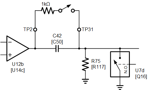
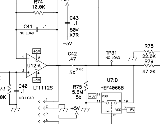
Here is a diagram for clarity. I've labeled components both for the SL and the [TDI/TDIpro]. Note that only the SL has test points. I have never tried this mod so I don't know what the results will be. The purpose of C42/R75/U7d is to eliminate DC offsets and reduce bounce-back noise but maybe it's overkill. If all you want to do is short C42 then I recommend lifting pin 10 of U7 [or removing Q16] or cutting the trace.
-
The AQ coil is currently on my TDI Pro, but the same can be done to the SL. For either you would need to reprogram the micro because that's what sets the timing. Only the original 200 TDIs had a timing circuit you could easily modify.
-
Output of the opamp. The C42 mod should have little to do with coil size. The purpose of C42 is to remove DC offsets before the final gain amp, which has to do with the circuitry and not the size of the coil. As Melano says, as you crank up the gain of the final amp (with the GAIN control) the DC offset gets gained up and can cause noise issues. I've never done this mod so I can't otherwise comment on its effectiveness. The absolute values of C20 and C21 don't matter much, even 10% caps are fine. Just make sure they match each other within 1%.
-
The caps can be just about any film-type: polypropylene, polystyrene, PPS, etc. What you want is a cap with low microphonics. Then you want to match the 2 caps to 1% or better. So if you get 2% caps, order 4 or 5 of them and then hand match two of them with a cap meter. On C42, I would not put a dead short there, rather put a 1k resistor across it. The reason is, there is a switch (U7d) that grounds that node and by shorting C42 the switch now grounds the opamp output (U12a). That's called "opamp abuse" and no one wants to be accused of that.
-
As it turns out, the factory TDI coils are a major performance limitation. I've adapted an Impulse AQ coil to run on the TDI and can then reduce the minimum delay to 6us. It's still not gonna run like a Minelab, but it is a little more respectable.
-
On the bright side, the patent expires Nov 3, 2024.
-
Sorry, ignorance of the law isn't much of a defense. Plus, it's documented that everyone here knows of the patent issue. I don't think ML would ever come after an individual who brings a Q80 into the US, but if they did, the first thing they would do is issue a letter of infringement and demand surrender of the unit. That would probably be the end of it, unless the infringer would rather dance with ML than kiss $700 goodbye. P.S. -- Discussion of intentional infringement, such as encouraging someone to go to Canada and buy a Q80 to bring back, can be considered "inducement to infringe," also illegal. All I'm sayin' is, "Be careful what you say in public."
-
Keep in mind that if you buy a Q80 in Canada and then take it into the US you will be personally infringing the ML patent and legally exposed. I can't imagine that ML would go after an individual but you never know. Loose lips enable lawyers to buy expensive ships.
-

The Nail Board Test And Sensitivity
Geotech replied to NCtoad's topic in Metal Detector Advice & Comparisons
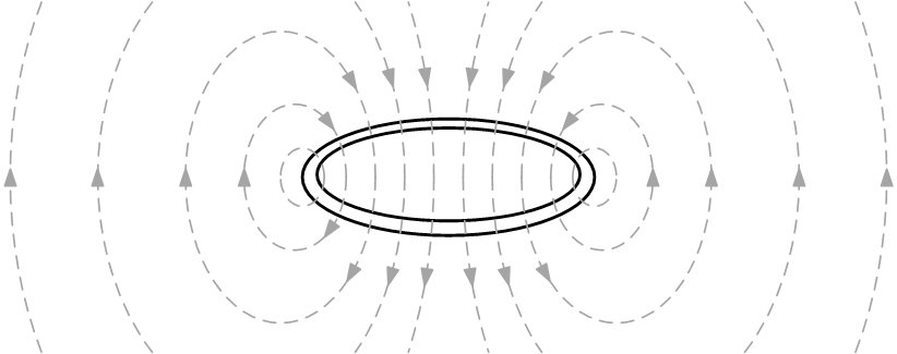
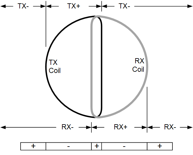
Magnetic fields form enclosed loops of flux; here is what it looks like for a coil: The flux has direction which is equivalent to polarity; let's call the downward flux through the center to be "positive" and the returning flux around the outside to be "negative." This is obviously the case for a TX coil but the field received by the RX coil has the same polarity: flux running through the center of the RX coil is positive and flux that runs to the outside of the coil is negative. Now put the TX & RX coils together in a DD coil and mark these regions: Basic math: (+) x (+) = (+) (+) x (-) = (-) (-) x (-) = (+) So the overlap region with +TX and +RX will produce a positive signal, but so will targets outside the perimeter of the coil although they will be weak. The areas inside one coil but outside the other produce negative signals that the detector ignores.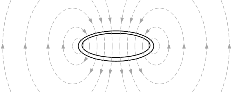
-
I used to have several Compass detectors. The first thing people lost was the battery cover.
-
The Nail Board Test And Sensitivity
Geotech replied to NCtoad's topic in Metal Detector Advice & Comparisons
Yes, that's what I mean by longitudinal. A nail creates a double beep because it has a maximum return signal when the coil's magnetic field aligns with it. Here is an illustration The arrows show the direction of the coil sweep. The magnetic field bends outward and the nail will have a maximum response at points (a) & (c), while minimum at (b). A coin is the opposite; it will have a maximum response at (b). So imagine a nail at (a) and a coin at (b); as the coil sweeps over they will both have a maximum response at the same point in the sweep. This is independent of recovery speed, it's just geometry.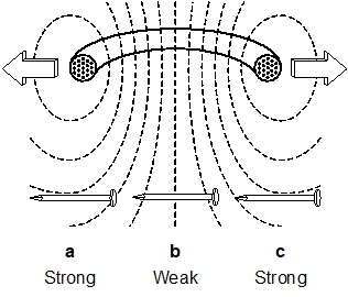
-
'839 is narrowly defined to cover sine-weighted demod clocks. You can avoid the patent by using square-wave demod clocks, which is likely what Garrett & XP did. I live 20 miles from Canada, unfortunately no detector dealers in Grand Forks. I had planned a drive up to Jasper in a couple of weeks but the Kelowna wildfire has caused travel restrictions. The use of sine-weighted demodulation dates back at least 100 years in tube radios, and at least the 1980s in software radio architectures. '839 is one of those patents that should never have been issued, as it's a commonly-known technique simply applied to a metal detector, which is otherwise just like any other quadrature demodulation application (like your cell phone). There was no actual invention here.
-
The covers were plastic that snapped into the hole.
-
"toddm32" would be Todd Marshall, who runs the Centerville-West White's repair facility.
-
For a color LCD, the backlight usually degrades/fails before the actual screen. The V3 uses a transflective LCD so it can run without a backlight, and doing so will extend its life. But even the screen itself can degrade, and excessive heat will speed that up. So ignoring the backlight, age is more of a factor.
-
White’s TDI Battery Modifications
Geotech replied to BeachBunnyTRHunter - DP's topic in White's Metal Detectors
Soldering tips: Before removal, apply a liberal amount of lead-based solder to each pad. The lead-free stuff that's on the board is hard to reflow and adding a big mass of lead solder helps tremendously. On the FET, bend/lift the individual pins off their pads before attacking the body. On the resistors, crack the resistor body and then you can remove the halves easily. A desoldering heat gun is the proper method. As cheap as $15. -
Whites TDI SL 5 Battery 20 Volt Pack. What Have I Done...?
Geotech replied to CaliGold's topic in White's Metal Detectors
Yes, 2-3W on the resistors and at least a heat sink on Q4. -
Whites TDI SL 5 Battery 20 Volt Pack. What Have I Done...?
Geotech replied to CaliGold's topic in White's Metal Detectors
3 components are subject to overheating: Q4, R9, and R14. R9 should be 1000Ω and R14 = 680Ω, I think they are both 1W. Most likely Q4 has been partially damaged, enough to alter performance but not enough to kill it. When jacking up the battery voltage these 3 components really should be upgraded for add'l power handling. -
Yeah, that looks like a faulty display. It's good to know there might be a direct replacement. When Sharp obsoleted that display we looked for a replacement but there was none at the time.
-
The best I can do is a schematic for the RB5, which was the middle sister in the RB family (RB7/RB5/RB3). It should be very close to the RB7 circuit as there were only minor differences in the machines. With only a quick look, I'd say the burned transistor is Q115 which regulates the +8V supply. You can replace it, but there may be another problem downstream that caused it to burn. And, yes, it uses 2x12V AA battery packs, easily found online. BH_RB5.pdf
-
Trying to sub a color display is tricky. Did you compare the data sheets to make sure the flex tail pinouts were the same, and that the timing was the same? The fact that the sub works at all suggests they are very close, but the black bars may be due to a timing difference.
-
Sorry, I missed "with the coil off." Yup, 25mA is bigly wrong. Sounds like it's not powering down. Could be software, I'd start with a reprogram. But there also might be a controller MOSFET that's gotten shorted.
-
Polish Pi Metal Detector
Geotech replied to Joel - cacadordereliquia's topic in Metal Detector Advice & Comparisons
The values look reasonable to me. T3 might have the collector-emitter swapped, that's the only thing I spotted. -
25mA sounds reasonable. What does "discharges completely" mean? Is that when it stops running? If so, 32 hrs also sounds pretty good, but I don't know what is normal.