Chet
-
Posts
219 -
Joined
-
Last visited
Content Type
Forums
Detector Prospector Home
Detector Database
Downloads
Everything posted by Chet
-
I would be interested; but it would be nice if they would set and stick to an expected market price at the release time. Instead of starting at a ridiculously high price then incrementally lowering it as the initial sales drop off. I think the GPZ 7000 started around $12000 then finally leveled off at around $8000.
-
Going by weight; this could be the expensive prototype.
-

Treasure Coast.... Not!(at Least For Me Lol)
Chet replied to IdahoPeg's topic in Minelab Equinox Forum
Outstanding find Peg! I hope you find more, Chet -
Dan I have an aftermarket lower shaft that is 30". I don't remember who sold it. Chet
-
GPZ Suddenly Not Balancing Out The Ferrite
Chet replied to flakmagnet's topic in Detector Prospector Forum
Flakmagnet I have had this problem a few times. Find some mild ground then try to ferrite balance for 2 to 3 minutes. If that doesn’t work then RESET ALL settings. Then try a long ferrite balance again. Then restore individual favorite settings and turn on the GPS and WM-12 if you use them. Have a good day, Chet -
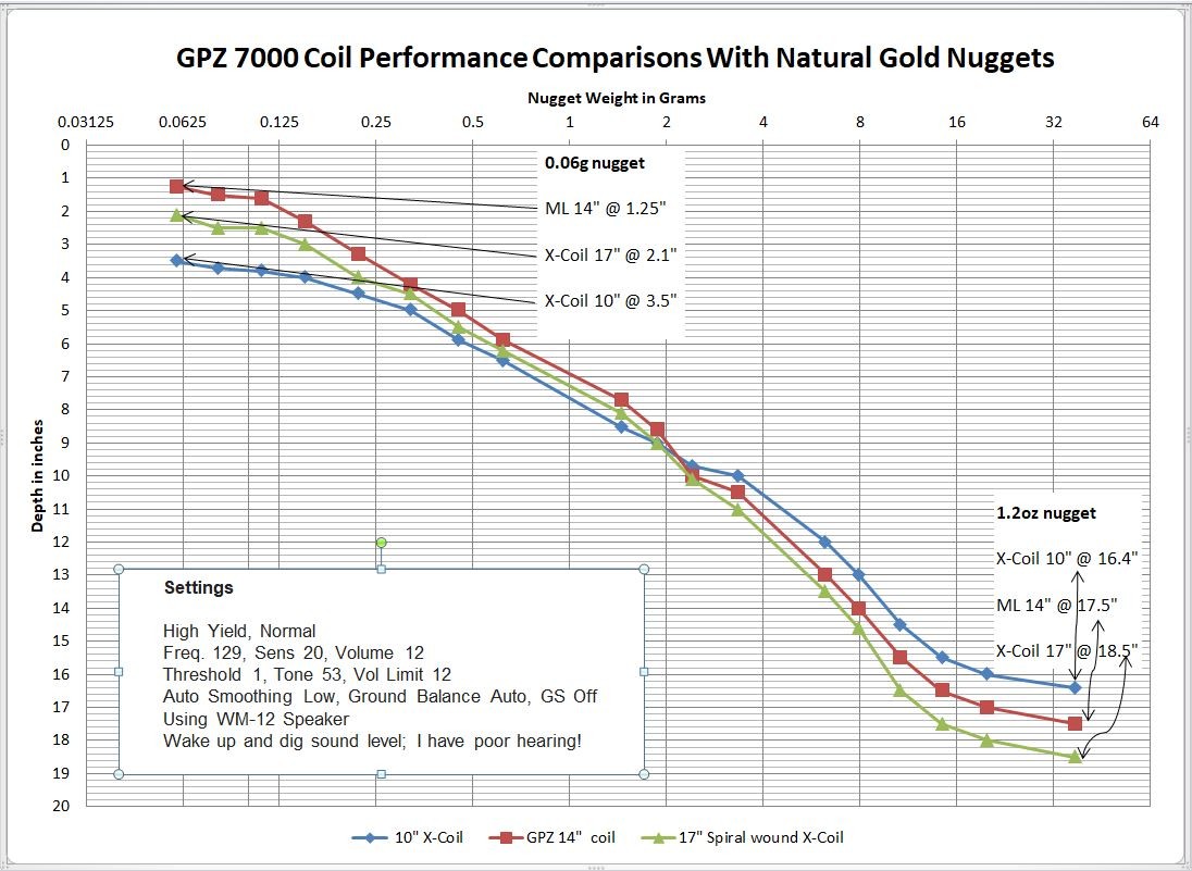
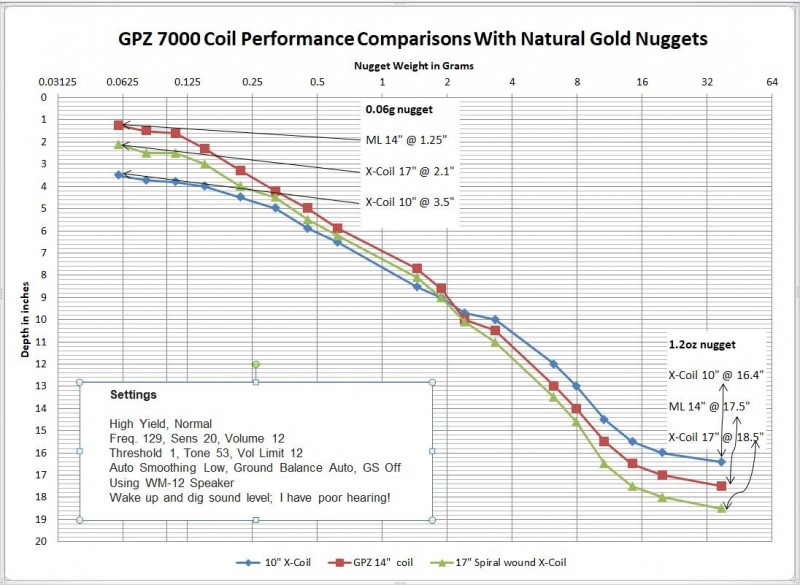
Hi GB_Amateur The detector applies the same pulse power to the coil regardless of the coil size. In a small diameter coil most of the magnetic lines of force that are created from that pulse are confined to a small focused near field. At far field the lines of force are spread and not focused. In a large diameter coil the magnetic lines of force are spread over a larger area at near field. But at far field they are denser than what is possible from a small coil at that distance. So the rule of thumb is; small nuggets are found with small focused coils at shallow depths. Larger nuggets are found with larger coils at deeper depths. So the chart shows how the 10” X Coil performs very well on small nuggets as expected until its near field loses to the larger coils far field advantage at deeper depths on larger nuggets. That point is where the 10" coil data crossover occurs in the chart. Many GPZ 7000 owners have desired a smaller coil for smaller nuggets at reasonable depths. Although this 10” X Coil is noisy it is still a useful tool in the pursuit of small nuggets. The chart also shows that the Spiral Wound 17” X Coil has a small depth advantage and more ground coverage when compared with the GPZ 14 coil. Have a good day, Chet
-
Steve I only put dirt in to fill the hole when I pulled the pipe out. Rye Patch is so hard on tires; lost another one this trip; lost a lot of gold buying tires in Winnemucca; lost a day of detecting; just call me a loser lol😀. Rye Patch temperatures are hit and miss for a while now. Have a good day, Chet
-
I agree that the coil is seeing the connectors at a close distance. I will do some more testing on this but the results of my depth comparison testing did not show any noticeable performance problems. The coils magnetic field has fixed disturbance at all times from the copper cable through the copper and solder in the control box to the battery. I used the GPZ 19 cable for the X Coil adapter cable. The two new connectors were in place on all three X Coils when I compiled the coil depth comparison chart data. Each coil was successfully balanced on the ferrite core before testing. The GPZ 14 coil that was used in the test has the original cable with no new connectors installed. The smallest nugget tested was a 0.06 gram. I will do some performance testing on this next month while in Arizona. I will start with the can taped onto the shaft as a worst case condition. Have a good day, Chet
-
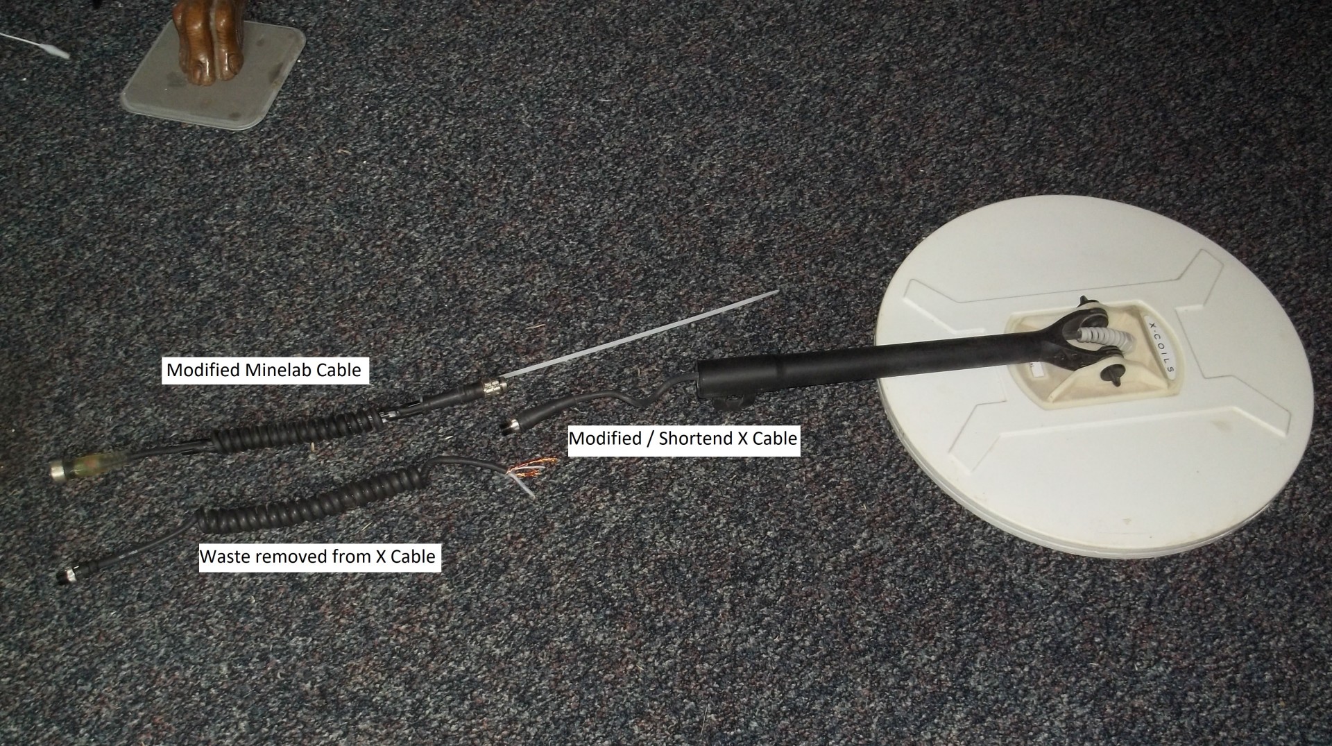
I did the Minelab cable cutting and soldering differently than specified by the manufacturer. Instead of cutting the cable near the Minelab connector I cut it below the Minelab curled cord and installed the 5 pin connector at that location. After the connector was installed and marine grade shrink tubing was applied a plastic tie wrap was attached with another piece of shrink tubing. This is used to pull the cable out of the lower end of the upper shaft since the Minelab curled cord retracts it out of reach. I then used a heat gun to soften and straighten approximately 8 inches of the lower X Coil curled cord. Cut it at that point and attached a new connector at 8” above the lower shaft. I have all three X Coils setup with three new lower shafts attached. This modification allows quick easy change of coils in couple of minutes. It is reasonable to be concerned about interference from the two connectors being located so close to the coil. This is not a problem since the detector only detects motion change relative to the coil. A simple experiment will demonstrate how the detector nulls out metal that is not changing position relative to the coil. Place a small test target on the ground with an aluminum soda or beer can about 2 feet from it. Swing the detector over the small test target. You will only hear the response from the large can. Now tape the can on top of the detector shaft 2 feet from the center of the coil. Now swing the coil over the test target and it will be detected. With the can attached the detector it will sound off as you lift and lower the detector to the ground since the coil is remaining flat while the shaft and can are changing position relative to the coil. In normal detecting when setting the detector down or lifting it I hear this sound-off with the 17” x 12” coil but not with the 10” or the 17” round coils. There is no effect during normal detecting since the coil is not tilting or changing position relative to the shaft. Have a good day, Chet

-
Fred For the X Coils prices; it varies with the exchange rate; please PM Davsgold for the current prices. Chet
-
Rick I look forward to it. Chet
-
Hi Fred I cannot justify the monetary return on investment of the GPZ 7000 detector, GPZ-19 coil, the X Coils, and all of the travel and man hours on a dollar return basis LOL. 😀 Likewise I can’t justify the many venison or salmon steaks that probably costed out at more than $50 each in my younger years. LOL😀 I guess the best return is well-being and the health benefits of an enjoyable activity. Have a great day, Chet
-
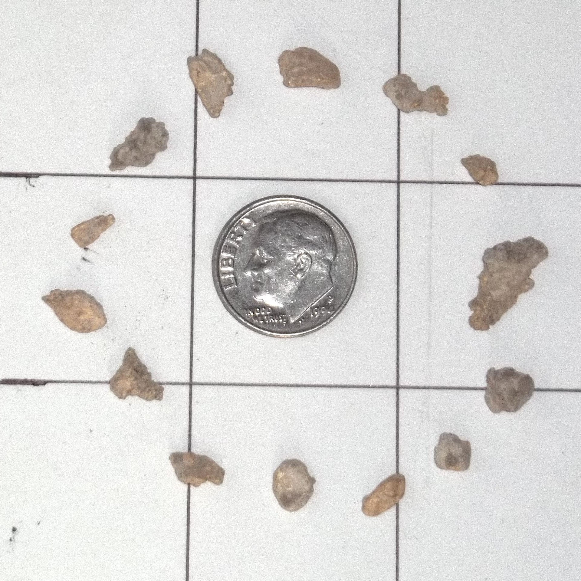
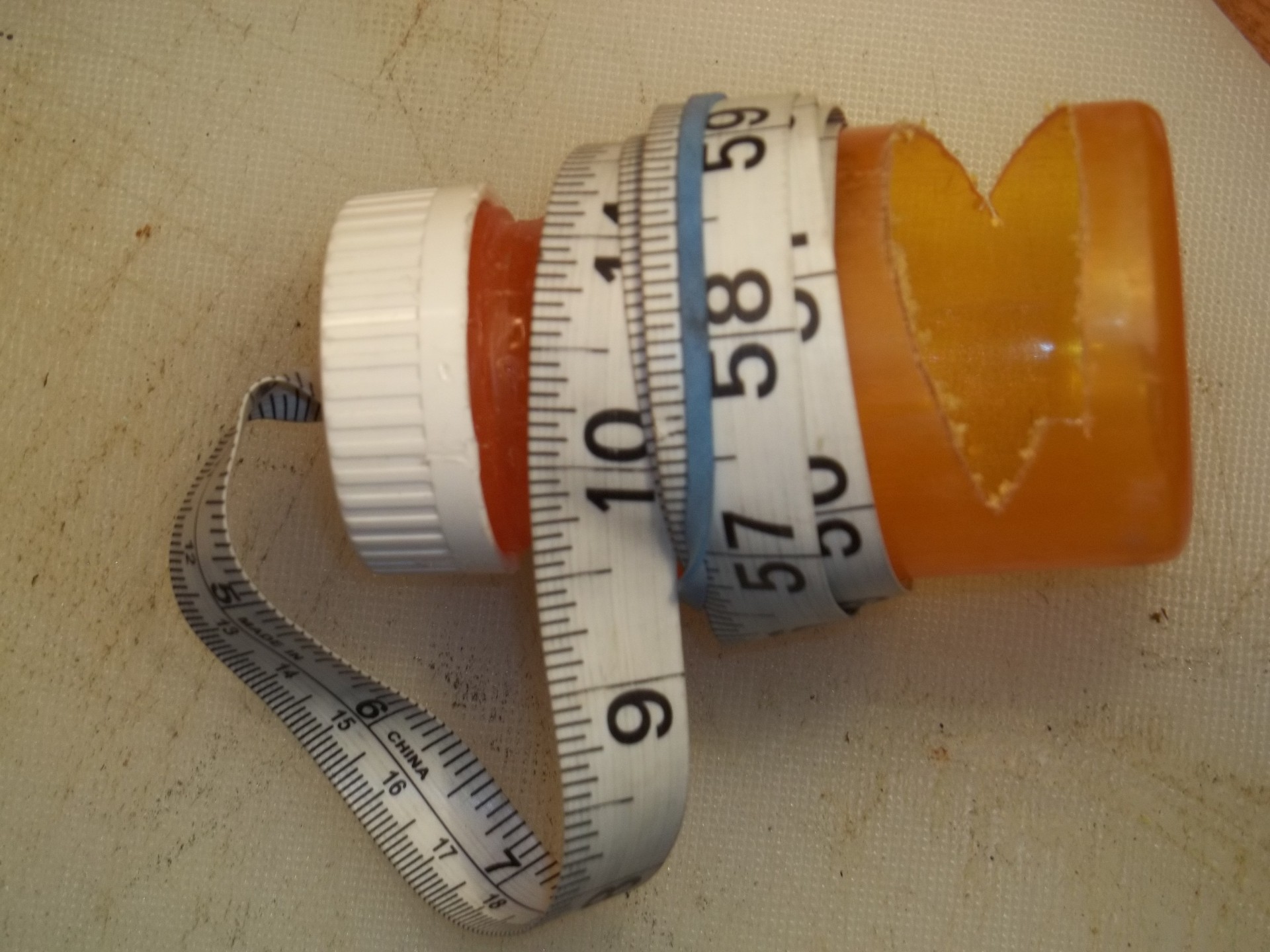
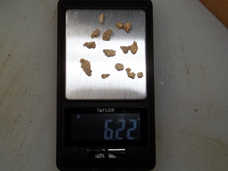
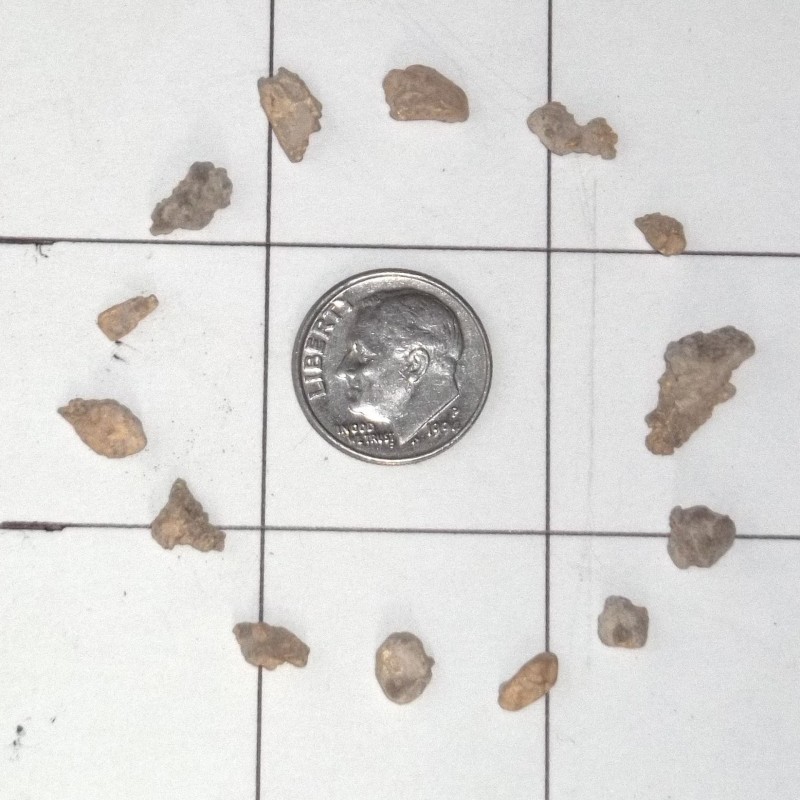
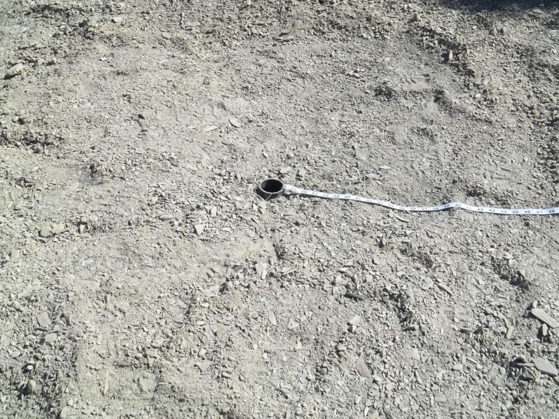
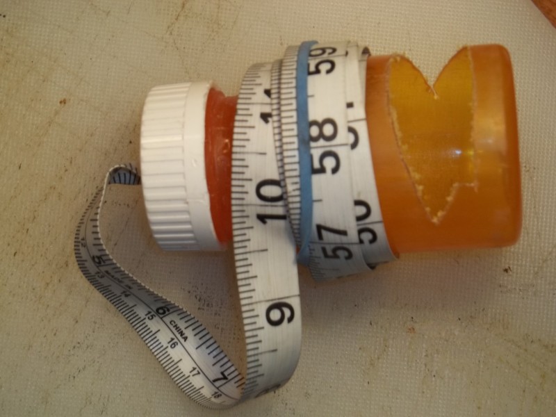
I just got back from Rye Patch, Nevada; found 14 small nuggets; 6.2 grams total. I found nuggets with all three of my X-Coils; 10” round bunch wound; 17” round spiral wound; and 17”x 12” elliptical spiral wound. I have attached a chart that is compiled from testing of the 10” round and the 17” round coils as compared to the Minelab GPZ 14 coil. The testing was accomplished in a Rye Patch gully by placing a two foot PVC pipe into a freshly dug hole. Gold nuggets of various sizes were lowered in a medicine bottle by a cloth measuring tape. This test was for my own relative comparisons; so those that want to critique the methodology feel free to do it another way. Two obvious depth improvements would be gained by increasing the Threshold setting and using headphones to listen for barely perceived target responses. After discussions with Lucky Lundy and Gerry McMullen I now have found a middle ground that works for me with the following settings; High Yield, Normal Freq. Auto, Sens 20, Volume 12 Threshold 1 to 27 depending on EMI noise level Tone 53, Vol Limit 12 Auto Smoothing Off, Ground Balance Auto, GS Off The 10” is very sensitive but noisy. When roaming across the desert it has me swinging back over false targets much of the time. But it works quite well to slow down and get into small openings between the sage brush and close to bedrock in narrow gullies. Some quick checks make me think that the 17”x 12” will have similar depth performance to the GPZ 14. But will cover three inches more ground on each swing. I will chart some depth comparisons when I get time to do some more testing. I use the 17” Spiral Wound Round coil when I want to cover a lot of desert. The extra inches in circumference with a little extra depth penetration over the GPZ 14 coil is an advantage. At this time I am retiring the Minelab GPZ 14 and the GPZ 19 coils. I have no connection to X coil, or to Davsgold except as a customer. X Coil and Davsgold have both been very responsive to my emails. Have a good day, Chet
-
Norvic, that’s good information and I will use your method. I will initially go to Auto Ground Balance mode to speed up the process. Then return to Semi Auto Ground Balance mode. If that fails then “Reset All” may save a walk to the truck to change coils? Have a good day, Chet
-
I don’t have an X-Coil yet. But it appears that resetting the GPZ default settings in the Menu may provide a method to recover from an X-Coil ferrite balance problem. I tried the following experiment. Use headphones plugged directly into the back of the GPZ for this procedure. 1. While in Manual Ground Balance mode; upset the ferrite balance by holding the Quick-Trak button in for about 15-20 seconds while waving the coil over a chunk of iron. 2. Do not press the Quick-Trak button for this step. Verify that the ferrite balance is upset by waving the coil over the yellow ferrite core. Note the loudness of the ferrite response. 3. Page through the Menu to “Reset Settings”; open it and move to the right to select the Check mark; select it. This restores the factory default settings. It appears that it may to also set the ferrite balance to a reasonable default value. 4. Now wave the coil over the yellow ferrite core. The loudness of the ferrite core should be greatly diminished. 5. Restore individual favorite settings and turn on the GPS and WM-12 if you use them. I did this in my back yard with terrible EMI from the neighborhood. So even though it appeared to work it needs to be verified away from EMI. Have a good day, Chet
-
I have the 10” and 17” X-Coils on order. My decision to purchase them is based on my thoughts/opinions of possible improved performances are as follows; The lowering the X-Coil transmit coil approximately 2cm/0.75” creates an exponentially greater target signal return to the receiver coils. DOD receiver coils are wired in series (voltage adding) so that with a large target the returned signals are combined effectively into one centered search lobe similar to a Mono coil. A very small shallow/weak target normally does not return enough signal strength to both receive coils to be formed into a Mono like search lobe. Thus they are predominantly detected in the more sensitive areas near the windings. The lowering of the X-Coil transmit coil approximately 2cm/0.75” creates exponentially greater signal strength from a small target. This can produce enough signal from some small targets into both receive coils to provide a Mono coil like search lobe. This will be most evident with smaller coils that concentrate the transmit energy into a smaller area. The exponential transmit and receive gain/sensitivity and resultant depth gain of the X-coil is similar to scraping away the surface debris to get closer to the target. At the same time receiving exponentially a louder and sharper response. The larger X-coils that have the transmit coil wound in some form of a spiral that should have some improved performance as seen in other spiral wound commercial coils. Some performance gain may have been made by changing the number of turns in the transmit coil and/or receive coil. They could be altered within reasonable design limits of the electronics. Some of the pros and cons of these coils have already been discussed. More experiences and reports from the field will be interesting. Have a good day, Chet
-
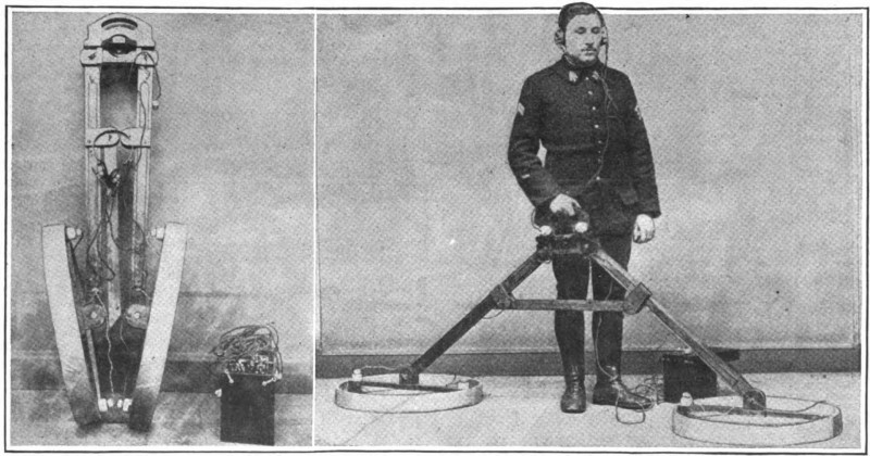
Hi Rick In most detector coils there is a conductive coat of black paint that forms a Faraday shield between the coil and the ground to reduce electric capacitance effects. Is there some kind of shield that is not shown in this photo? I don’t see a shield in the Minelab photo either. Perhaps it is not needed in the GPZ 7000 Zero Voltage Transmission (ZVT) design? Thank you for this interesting photo and have a good day, Chet
-
The X Signal term has been used in metal detector technology for many years. The X Signal is the magnetic effects generated by the transmitter and detected by the receiver. Another received signal used in VLF detectors is a resistive R Signal. This website will automatically download a .pdf file that may help some on this subject. https://www.iaom.info/wp-content/uploads/06mdpkgwc17.pdf The original GPZ equations may have had problems with auto ground balancing tracking because of the non-linear effects that the nanoparticles created in the magnetic X Signal returned from highly mineralized soil. Thus the Ferrite balancing routine was incorporated to provide a workaround for the problem. When detecting in Nevada after a rainstorm the GPZ gets a lot of ground noise and on buried test targets it loses depth. A combination of effects caused by the wet desert soil should be considered; soil temperature is affecting the nanoparticles; wet salt may be causing some kind of magnetic change in the soil; wet salt may be causing more conductivity loss through the soil. Have a good day, Chet
-
My understanding of the how Ground and Ferrite balancing may work??? Soil contains minerals such as iron and other particles that create a somewhat constant Ground signal that can be averaged and fed into the GPZ 7000 mathematical equations as a Ground tracking value. Ground tracking across different up/down distances of unleveled ground is possible as long as the magnetic ground response is linear. Linear meaning that as the coil goes close to the ground and then away from the ground a uniform Ground signal strength change is expected. The GPZ equations know from constant Ground tracking and/or you pumping the coil up and down periodically what kind of linear/uniform Ground signal response it should receive from the ground at different heights. Superparamagnetic particles normally do not have magnetic hysteresis or B curve like a small particle of iron. They do not retain a magnetic charge or north/south alignment like a small iron particle will. They change characteristics as the soil changes temperature. They are easily magnetically saturated. When the soil contains great numbers of these Superparamagnetic particles and they become saturated they generate a non-linear/non-uniform Ground signal that disrupts the GPZ ground tracking and target processing equations. To mitigate this X Signal problem the Ferrite balancing routine is providing a value into the GPZ mathematic equations to handle normal soil X Signal levels. The Ferrite value may be weighted in the different ground modes Normal, Difficult and Severe. The Superparamagnetic particles nearest the overlap of the Transmit and Receiver windings near the center of the coil are the most susceptible to becoming saturated. The Transmit winding is 2 cm above the Receiver windings to increase the distance to the soil and reduce the stronger magnetic lines of force that are close to the transmit coil from saturating these particles. Why is Proper Ferrite and Ground balancing important? The transmit pulse energizes the metal target that causes magnetic currents to generate a short duration magnetic field that is sensed by the receiver coils. The detectable duration of the target return is called the Time Constant of the target. Small gold nuggets have a very short Time Constant as well a weak signal return. Larger nuggets, bullets, nails, and junk have long Time Constants. Soil has a Time Constant that is similar to small nuggets. Small nuggets that have Time Constants that are shorter or longer than soil can be detected. Small nuggets that have the same time constant as soil may not be detected. For small nugget detection it is important that accurate, narrow Ground and X Signal values be maintained. Have a good day, Chet
-
Referencing this patent; which discusses the GPZ 7000 and possible coil options; United States Patent Application 20130154649 CANDY; Bruce Halcro June 20, 2013 TRANSMIT SIGNAL OF A METAL DETECTOR In searching using edit and find functions for the word “Saturation” and “X” it came up with references that place the Transmit coil 2cm above the receive coil to reduce saturation of the soil. This 2 cm is important in highly mineralized ground that effects the processing of the X signal response. The X signal occurs from non-linear reactions of magnetic components of saturable ground that have the property of viscous superparamagnetism. Superparamagnetism is a form of magnetism which appears in small ferromagnetic or ferrimagnetic nanoparticles. It is important for the GPZ 7000 to avoid saturation of the soil so as to reduce the X signal response to a manageable level that can be processed out and allow weak gold responses to be processed. What may be happening with the X coils on highly mineralized ground? Going by the descriptions stated in the forums; the coils are flatter than the factory coils. This implies that the 2 cm separation between the lower receive coils and the upper transmit coil is not there. This would allow the transmit coil to be closer to the soil and disturb the X signal response when over highly mineralized soil. A possible solution that should be tried in the field on hot ground is to swing the coil 2 cm/0.79 in. higher than normal. Some experimenting may be required to resolve the problem that Andy had with the 10” X coil. Perhaps ferrite balancing on quiet soil or in the air. Once it is accomplished it is stored and will return to the same setting when powered up again. Have a good day, Chet
-
If you want to make a backup/replacement One-wire ID chip for the coil here is what you will need. The video explains the process rather well. It will require that you shave off enough plastic on the 7 pin plug to read the chip number. https://www.youtube.com/watch?v=r2T78o7oxfQ&t=9s https://www.ebay.com/itm/Serial-EEPROM-FLASH-PROGRAMMER-1-5-5V-ICSP-USB-24x-25x-93x-95x/301984133071?hash=item464fa82fcf:g:acAAAOSwjVVVp-Gd https://www.digikey.com/products/en/integrated-circuits-ics/interface-specialized/754?k=one-wire Have a good day, Chet
-
Jason I apologize, reading back I saw that you had already addressed the bulkhead connector as a possible problem. And I agree that the software should be reloaded. Have a good day, Chet
-
Condor What kind of error do you get; coil not connected; coil overload; or some other error? Minelab detectors are normally pretty forgiving in their coil circuity and survive most faults. So I would first suspect and look for a bad connection in the bulkhead female connector. The original large Minelab 7 pin connector threaded ring should be almost flush with the bulkhead when the plug is completely seated. The large Minelab 7 pin female bulkhead connector may have a female pin that has been damaged or broken within the plastic encasement. With a bright light and a toothpick inspect each female pin for unusual looseness or movement. Maybe a solder joint on the backside of the bulkhead connector has failed. The only way to properly check this would be to open the Bulkhead and check continuity through each of the 7 pins. Unfortunately this is not a simple check and repair for the average person in the field. And it is possible as others have stated that it will require service from a Minelab repair center. Good luck and hopefully a better day, Chet
-
The problems were with the Minelab 14”coil. I am on the list to purchase some X-coils. I look forward to giving them a run in some heavily detected areas. Have a good day, Chet
-
Andy Though not the same as your problem; I will share some similar severe problems that I have had with ground balancing. I normally run in High Yield; Normal with Semiautomatic ground balancing mode. My problems were self-inflected by allowing the coil to set on an iron reinforced floor while connected to my computer for transferring Find points and Way points. Another was caused by reviewing Find points and Way points while inside the car during a rainstorm. While the coil was setting on the passenger side floor pan. In both cases the detector sounded like a machine gun as it was sweep across mild ground. The ferrite core was of no use until several minutes of waving the coil over the ground wile holding the trigger in. Another similar problem occurred when trying to ground balance on the ferrite core near a solar system. The solar charge controller was generating EMI that prevented it from ground balancing. Moving away about 100 ft cured the problem. Have a good day, Chet