Chet
-
Posts
214 -
Joined
-
Last visited
-
Days Won
1
Content Type
Forums
Detector Prospector Home
Detector Database
Downloads
Everything posted by Chet
-
I received some California LiDAR data from Matt. It is very easy to install and view in Google Earth. It is very interesting. I think I found a few rows of stacked rocks in a few deep gullies and/or along some stream beds. I will check them out this spring or summer. Caterpillar logging trails and caterpillar built fire breaks appear in many places. Mostly on hillsides and ridges. Have a good day, Chet
-

GPZ Anybody Else Having Issues With Undergrowth
Chet replied to Condor's topic in Minelab Metal Detectors
My first GPZ, about 3 years ago had a similar problem. In High Yield, Normal it would run great most of the day. In the afternoon when the battery was around 50% down it would sound off like you describe “detecting over a bed of tiny birdshot”. I could charge it at the car for 10 minutes and it would settle down until the battery was again down around 50%. I think an internal voltage regulator must have been failing. The replacement detector cured that problem. My standard settings are High Yield, Normal and 20 Sensitivity. Most of the time wet grass, mud and water have no effect. But in some areas at times I still experience the same severe effects in wet grass. Chet -
Scams Out There
Chet replied to Johnnysalami1957's topic in Metal Detecting & Prospecting Classifieds
That same bogus GPZ 7000 ad is back on eBay again!! https://www.ebay.com/itm/Minelab-GPZ-7000-All-Terrain-Gold-Metal-Detector/292977609828?_trkparms=aid%3D111001%26algo%3DREC.SEED%26ao%3D1%26asc%3D20160908105057%26meid%3Db7912ae7cf7f4f40bcf92f59bd96da82%26pid%3D100675%26rk%3D1%26rkt%3D15%26sd%3D292977609828%26itm%3D292977609828&_trksid=p2481888.c100675.m4236&_trkparms=pageci%3A554825e1-37c4-11e9-8000-74dbd1805566|parentrq%3A1cbad2951690ad793fa57401fff2a2c3|iid%3A1 -
GPZ Anybody Else Having Issues With Undergrowth
Chet replied to Condor's topic in Minelab Metal Detectors
I have experienced the same severe effects in wet grass with both the GPZ 7000 and the GPX 5000. I just move on to the clear patches and skip the wet grass areas. The problem mostly goes away as the grass and ground dry up. It still detects the roots of Joshua trees and Barrow cactus. In between wet and dry seasons it sounds off as I swing back and forth between grass and bare areas. In this situation I allow the detector to automatically ground balance as I hunt as much as I can of each area in sequence. Have a good day, Chet -
Hi Green Those are some nice chunky nuggets. They haven’t been beat up, flattened and worn smooth by traveling for millions of years in an ancient river. Their size and shape are very detectable by most pulse induction detectors. They are typical of nuggets that are found closer to the original source of the gold. The three you show with your chart are typical of what is found in Californian hydraulic pits which are ancient river gravels. Have a good day, Chet
-
Hi Dave Thank you for clearing up my confusion on the cables. The reduction in weight and having a selection of different coils for different hunting situations will be a big gain if these coils are stable and get on the market. Have a good day, Chet
-
Hi Dave In your previous videos the coil cords where inside the shaft. In the new videos the cord appears to be spliced and outside the shaft. Can you describe the connections; especially on the stock GPZ14 coil? Do you think the temporary connections have any effect on performance? I like the test results with the 22” x 21” coil. Here in the US I run the GPZ19 in High Yield, Normal much of the time. It would be great to see the lighter weight 22” x 21” coil performance compared with the GPZ19 if you can fit that into some future testing? I do understand that High Yield, Normal timings may be noisy in your ground. Have a good day, Chet
-
Hi Dave Will they have some on the market soon? Thank you, Chet
-
Hi Lunk I made it to the south side of Franconia in March. I had never hunted for meteorites before so I dug everything. Using the GPZ 7000 resulted in a lot of deep and shallow junk. Evidently it was a WW II training area resulting in a lot of 50 Caliber bullets. There are a lot of small pieces of screen wire everywhere. The wire is on or near the surface so the magnet in the handle of my pick came in handy to quickly pick it up. I didn’t find any meteorites but I will try again in the future. Have a good day, Chet

-
Hi Dave Is this from the same manufacturer? Have a good day, Chet
-
Hi Sometimes after having the GPZ on for long periods while manually transferring Find Points and Way Points to my computer the GPZ is very noisy the next time out. When this occurs an extra-long balancing over the ferrite core cures it. Have a good day, Chet
-
Xchange 2 Compatibility With Latest GPZ Update
Chet replied to Nevada Brian's topic in Minelab Metal Detectors
Brian; thank you for starting this. Steve; I look forward to trying your procedures. Clay; thank you for the offer to help in this effort. Have a great day, Chet -
My GM1000 Methodology - Manual Versus Auto Sensitivity
Chet replied to Steve Herschbach's topic in Minelab Metal Detectors
Hi Steve Great write up; a lot of great information. Thank you, Chet -
Hi Peg Wow! Great Job! Have another great day, Chet
-
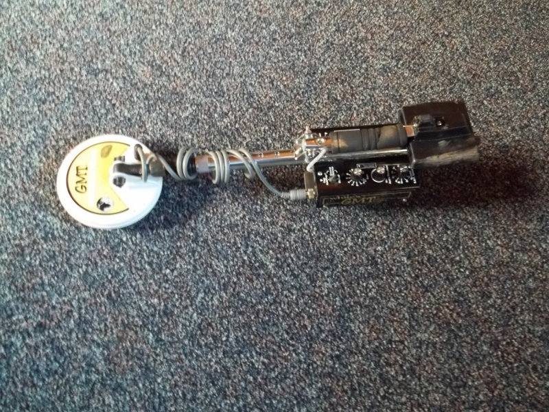
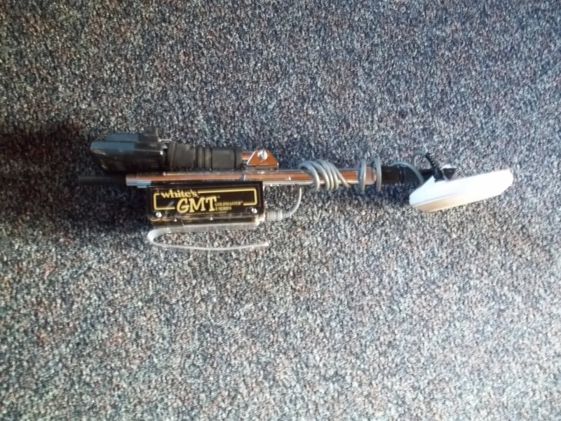
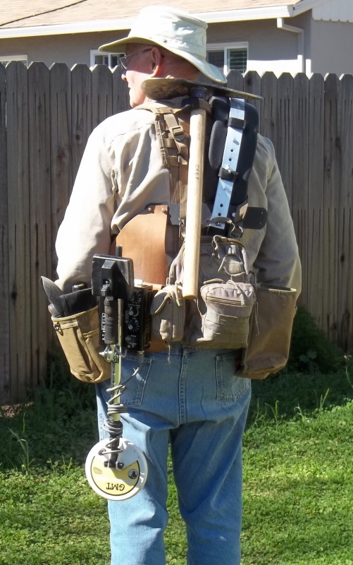
GMT Pin-Pointer I modified my GMT to fold down and hang on my pack belt. It works quite well with my GPZ 7000 with the monster 19” coil. If you lay the two detectors close together and manually tune the 7000 you will find a few relatively quiet EMI null frequencies. I normally run at frequency 22. When in use I lay the 19” coil behind me or far to side of the dig site to further minimize the interference. The GMT works well in the compacted length. It will still telescope out to full length for extended hunting in nail patches. Have a good day, Chet


-
Hi G.B. Thank you for doing these very informative mode comparison tests. The wireless microphone audio was a little weak and hard to follow at times; for clarity I have summarized my understanding of your tests as follows: Each test run was on the following targets in sequence that have been buried for more than six years: 1. a 22 bullet at 6” 2. a 22 bullet at 8” 3. a 22 bullet at 9” 4. a 22 bullet at 12” 5. a ½ oz piece of lead at 12” Do you know the shape and size? 6. a ½ oz piece of lead at 14” 7. a ½ oz piece of lead at 18” 8. a 10 oz piece of lead at 27” Do you know the shape and size? JP’s usual conservative settings were used which are..... • Threshold: 27 • Audio Smoothing: OFF • Volume: 8 (I use the B&Z booster through twin speakers) • Volume Limit: 8 to 10 • Ground Balance: Tracking • Gold Type Mode: General for solid heavy nuggets over 10 grams, High Yield for rough gold or solid nuggets 15 grams and down • Ground Type Mode: Difficult, because the ground here is nasty • Threshold Pitch: 60 • Ferrite Balance: Perfect at all times (regularly check it) First test run starts at 2+ minutes into the video; High Yield Gold Mode, Difficult Ground Mode Second test run starts at 6 minutes into the video; General Gold Mode, Difficult Ground Mode Third test run starts at 8 minutes 45 seconds; Deep Gold Mode, Difficult Ground Mode Fourth test run starts at 12 minutes; High Yield Gold Mode, Normal Ground Mode Fifth test run starts at 15 minutes 35 seconds; General Gold Mode, Normal Ground Mode Sixth test run starts at 18 minutes; Deep Gold Mode, Normal Ground Mode Do you have any information on shape of the large lead pieces? I look forward to your video of the GPZ 14 coil responses. Have a good day, Chet
-
Referencing high/low sounds associated with gold, this video is very interesting. Try to guess which sounds are from gold before the answers are given at the end of the video. Have a good day, Chet
-
JP On Using The New PRO-SONIC From Minelab
Chet replied to Steve Herschbach's topic in Minelab Metal Detectors
Steve, the WM 12 continues to work when the headphone jack is used. That is how I connected the oscilloscope up to both paths simultaneously to measure the 20 millisecond delay in another post on Bluetooth delay. Have a good day, Chet -
Some hear different sounds on different targets under different conditions. I have a difficult time with recognizing musical notes. The only musical instrument that I play well is the phonograph. Some complex functions are occurring to produce the unique and pleasing sounds of Minelab Pulse Induction detectors. So a high/low sound has two characteristics to consider; a change in volume and a change in tone. I will try to explain what is happening in target sounds. On the oscilloscope display; the vertical waveform envelope starting on the left is rising in volume to the top of the display; then decreasing in volume until near the center of the display. At this time the nickel is passing over the center of the coil. The sound volume is nearly off at this point. Then the sound increases and decreases again across the other side of the coil but at a lower volume than was heard on the left side of the coil. At the same time another function is occurring; if you look closely at the sound envelope it is made up of software programmed digital pulses that are being generated in a manner that generates a change in audio frequency tone as the volume is changing. The lower volume pulses at the beginning of the left side of the envelope are tightly spaced together which is a high frequency tone. The pulses spread apart as the volume increases which is changing to a lower frequency tone. At the top of the display the tone has reached its lowest tone frequency. Then the pulses become closer together as the volume decreases reaching a high frequency tone near the center of the display. The lower volume sound envelope on the right side of the display starts with a high tone and increases even higher in tone as the volume increases then decreases in tone as the volume decreases. There are many variables that effect target response sounds from Minelab detectors. Some are the size and shape, the distance from the coil, soil mineralization, ferrous, nonferrous, and speed of sweeping. During the test there was high Electromagnetic Interference from neighborhood computers, TVs and electric lines. The GPZ 7000 detector settings used to reduce the effects of EMI were as follows; High Yield, Difficult, Sensitivity 5, Frequency 60, Volume 6, Target Volume 12, Threshold 1, Audio Smoothing OFF, the coil was ferrite balanced on a cement floor with no rebar. The Frequency, Threshold, Sensitivity and Volume settings had the greatest effect on mitigating the EMI. The nickel was attached to the bottom of 16 ounce bottle of water. The bottle was suspended by a seven foot cord to function as a pendulum. In order to further mitigate EMI the nickel was within two inches of the coil on each swing of the pendulum. I had to capture many swings of the pendulum to find a waveform that was not clobbered by EMI. This same nickel buried in the field with a quiet environment and normal detector settings will generate a different waveform and an overall different target sound. There are some sample sounds at; http://www.victorianseekersclub.org.au/detector-sounds The sound of this setup was similar to the first sample ‘Inverted’ Gold Signal. Have a good day, Chet
-
There is more signal information to be gleamed and some of the easier and cost effective ideas will be built into future detectors ahead of other more expensive features. Many experience hunters can sense if it is a big chunk at depth or if it is a small nugget near the surface. In future models more depth and size information might be displayed in a % of probability value. That would be similar to what the White’s GMT does now for % of probability of the target being iron. Refer to the many posts by experienced persons stating the best settings to use under different ground and electromagnetic interference conditions. Future models will be able to evaluate those conditions and change modes and adjust to the environment without any operator actions. False targets such as clay hotspots and hot rocks have some different characteristics from metal objects. Another % of probability that it is a real target could be displayed. Digital / computer mathematic and statistical methods will continue to make improvements on these ideas and in other areas. It is a slow process due to the small market for metal detectors. Small detector companies cannot afford many engineers and computer software personnel. And they cannot spend years in research and development. They have to get attractive stable machines into the market to stay in business. If the market was anywhere as big as cell phones or television we would already have fantastic detectors at low cost. Have another good day, Chet
-
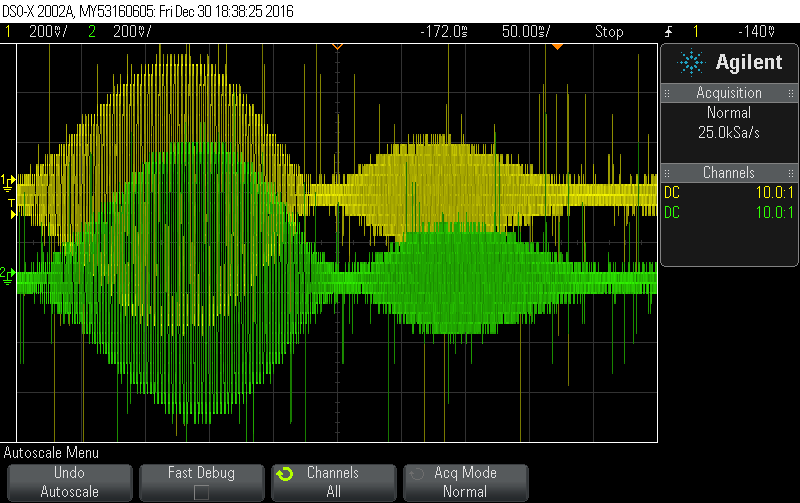
I couldn’t find a wireless delay specification for the GPZ 7000 WM 12. So I tested it. The attached oscilloscope display is the audio waveform envelopes from a US nickel passing over the GPZ-19 coil at approximately 40 inches per/sec. The upper yellow waveform is from the earphone jack on the back of the GPZ 7000. The lower green waveform is from the earphone jack of the wireless WM 12 receiver. The waveforms are sweeping in time from the left side to the right side. The entire display is divided into 10 horizontal increments of 50 milliseconds (0.050 sec.) each. The audio (wah-wee sound) created by the nickel is spread across 9 divisions (450 milliseconds) with the nickel crossing the center of the coil at approximately 4.5 divisions (225 milliseconds). Close measurement of the green trace displacement to the right indicates that the wireless WM 12 receiver audio is delayed by 20 milliseconds. The nickel speed of 40 inches per second is equal to 1 second divided by 40 = 0.025 sec. = 25 milliseconds to move 1 inch. So a delay of 20 milliseconds is less than a 1 inch position error which would be imperceptible during normal searching. When slowed down to pinpointing speed it would be a minuscule error. A 50 ms delay would result in an approximate 2 inch position error which at sweep speed is probably not that noticeable to most of us. Again at pinpointing speed it should not be a problem. For information; the scattered positive and negative spikes are noise spikes from the GPZ 7000 transmitter pulses. The wide bandwidth / fidelity of the oscilloscope allow it to capture these spikes. The spikes are too high in frequency for the human ear to hear. Electromagnetic Interference (EMI) that we randomly hear resembles the waveform envelopes shown in this display. This is somewhat technical so I hope I have made it understandable to some. Have a good day, Chet

-
Hi Clay Amazing! Great work; works fine with Chrome and Windows 10. Have a good day, Chet
-
I have used the Avantree Pro Bluetooth transmitter and receiver set for some time. They work great. The delay is 32 milliseconds (.032 sec). If you are swinging the coil at three feet per second you will hear the target (36” x .032) = 1.152 inches after you cross over it. When moving the coil slowing while pinpointing the delay is insignificant. If you purchase these be sure you are ordering the Low Latency Pro model. They have a cheaper set that has an unacceptable delay time. Have a good day, Chet
-
Hi Jonathan Thank you for the quick reply. That helps and gives me more to work with. Have a good day, Chet
-
Jonathan Thank you for much needed information; it provides a lot to work with the next time out with the GPZ 14 coil. I am eager to receive the GPZ 19 coil which is on order. A few questions: Is it the larger area of the 19” coil allowing it to obtain a better average measurement of the soil and mineralization to allow it to run smoother? Then does this smoothed average provide a better reference for comparison to provide a better target signal to ground noise ratio? In reference to; “correct range of coil motion in relation to the depth of the target”. Does this mean use wide coil swings for deep wide target responses and shorter coil swings for sharp narrow target responses? You use a B&Z booster with twin speakers. Is the B&Z booster just a better quality amplifier are is there some kind of signal altering occurring within it? Likewise is there something special with the twin speakers? Thank you for your assistance and have a good day, Chet